Home/
Registry/
Mercury/
Cougar/
1989-1997/
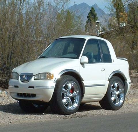
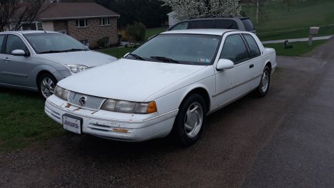
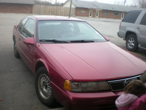
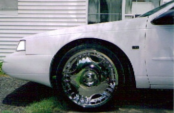
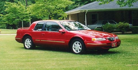
1997 Mercury Cougar/
Photo
supermotors.net/registry/media/713102
Ford Thunderbird/Cougar, Ranger, Explorer IAT & ECT Sensor Connector Pinout
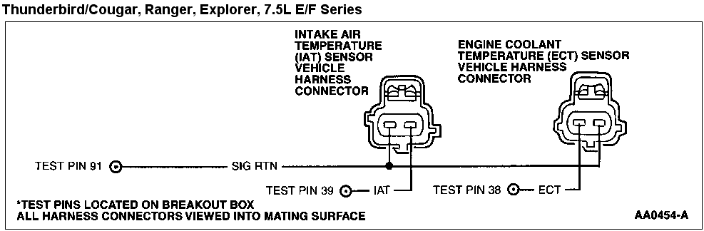
Ford 7.5L E/F-series IAT/ECT sensor connector pinout: SIG RTN on test pin 91, IAT on test pin 39, ECT on test pin 38, connectors viewed into mating surface.
Part of 1989-1997 Mercury Cougar Wiring Diagrams
This document is a Ford EEC wiring/pinout diagram covering the Intake Air Temperature (IAT) sensor and Engine Coolant Temperature (ECT) sensor vehicle harness connectors. It applies to the Thunderbird/Cougar, Ranger, Explorer, and 7.5L E/F Series (E-Series/F-Series) vehicles. The diagram shows both two-pin sensor harness connectors drawn as viewed into the mating surface, with their circuit connections traced to breakout box test pins used in EEC diagnostic testing: Test Pin 91 corresponds to SIG RTN (signal return), which is shared between both sensors; Test Pin 39 corresponds to the IAT signal circuit; and Test Pin 38 corresponds to the ECT signal circuit. Footnotes clarify that the test pins are located on the breakout box and that all harness connectors are illustrated as viewed into the mating surface. The figure carries the Ford illustration reference number AA0454-A. A technician can use this diagram to identify which terminal of each sensor connector carries the signal versus signal return, and to know which breakout box pins to probe when diagnosing IAT or ECT sensor circuits on the listed vehicles. No wire colors, resistance specifications, or year information are printed on the diagram itself.
Is this accurate? Sign in to help verify it.
Frequently asked questions
- Which breakout box test pin is used for the ECT sensor signal?
- Test Pin 38 corresponds to the ECT sensor signal circuit on the breakout box.
- Which test pin corresponds to the IAT sensor signal?
- Test Pin 39 is the IAT sensor signal test pin on the breakout box.
- What is Test Pin 91 in this diagram?
- Test Pin 91 is SIG RTN (signal return), which is shared by both the IAT and ECT sensor harness connectors.
- Which vehicles does this IAT/ECT connector diagram apply to?
- The heading lists Thunderbird/Cougar, Ranger, Explorer, and 7.5L E/F Series vehicles.
- How are the harness connectors depicted in the diagram?
- All harness connectors are shown as viewed into the mating surface, and the test pins are located on the breakout box.
Comments
More from this build
No comments yet.