Home/
Registry/
Mercury/
Cougar/
1989-1997/
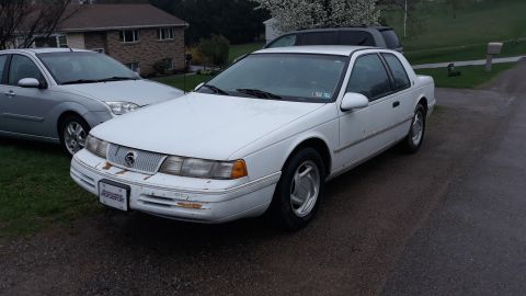
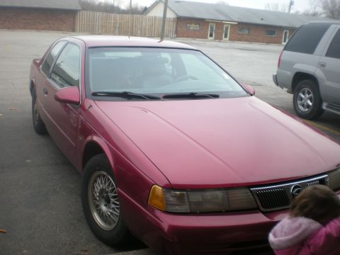
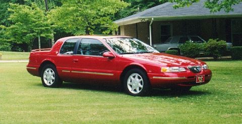
1997 Mercury Cougar/
Photo
supermotors.net/registry/media/713101
1996 Ford/Mercury Cooling Fan Wiring Diagram - CCRM, EDF/HEDF Relays & PCM

Wiring diagram for the engine cooling fan circuit showing EDF/HEDF relays, fan motor, constant control relay module, and PCM.
Part of 1989-1997 Mercury Cougar Wiring Diagrams
This document is page 33-1 of a factory-style wiring diagram covering the engine cooling fan circuit. Power comes from a 60-amp fuse (position 5) in the Power Distribution Box (referenced to page 13-2), which is hot at all times. Circuit 37 (Y) passes through connectors C122M/C122F, becoming circuit 38 (BK/O) through splice S123 into connector C138 at pins 3 and 4 of the Constant Control Relay Module (CCRM). Inside the CCRM are the EDF relay, HEDF relay, and a solid-state EDF relay control, with references to the PCM power relay (page 35-2) and pin 15 (page 33-2). Outputs on circuits 228 (DB) via splice S177 and 181 (BR/O) via splice S178 feed the engine cooling fan motor through connector C137; the motor has L, M, and H terminals and grounds through circuit 57 (BK) at G101. Circuits 197 (T/O) and 639 (LG/P) connect through C138/C280 to the Powertrain Control Module (pins 45 and 46, referenced to pages 23-7 and 24-7). Notes explain that the PCM monitors engine coolant temperature and A/C status to command fan speed.
Is this accurate? Sign in to help verify it.
Frequently asked questions
- What fuse powers the engine cooling fan circuit?
- A 60A fuse in position 5 of the Power Distribution Box (hot at all times), shown on page 13-2.
- What module controls the cooling fan relays?
- The Constant Control Relay Module (CCRM), which contains the EDF relay, HEDF relay, and a solid-state EDF relay control.
- What wire colors and circuit numbers feed the cooling fan motor?
- Circuit 228 DB (dark blue) and circuit 181 BR/O (brown/orange) run from the CCRM through connector C137 to the engine cooling fan motor; ground is circuit 57 BK to G101.
- How does the PCM decide when to run the fan?
- Per the diagram note, the PCM monitors engine coolant temperature and air conditioning status; when operation is required it signals the IRCM/CCRM to turn on the fan at the desired speed.
- Which PCM pins are used in the cooling fan circuit?
- PCM pins 45 and 46 (connector C280), connected via circuits 197 T/O and 639 LG/P; the PCM is shown on pages 23-7 and 24-7.
Comments
More from this build


No comments yet.