Ford 351M V8 Vacuum Routing Diagram - Calibration 9-71J-R10 & 7-72J-R11
Reference · 1977-1979 RancheroAll 2 vacuum routing diagrams
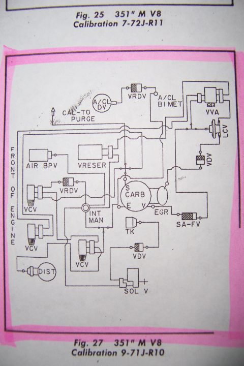
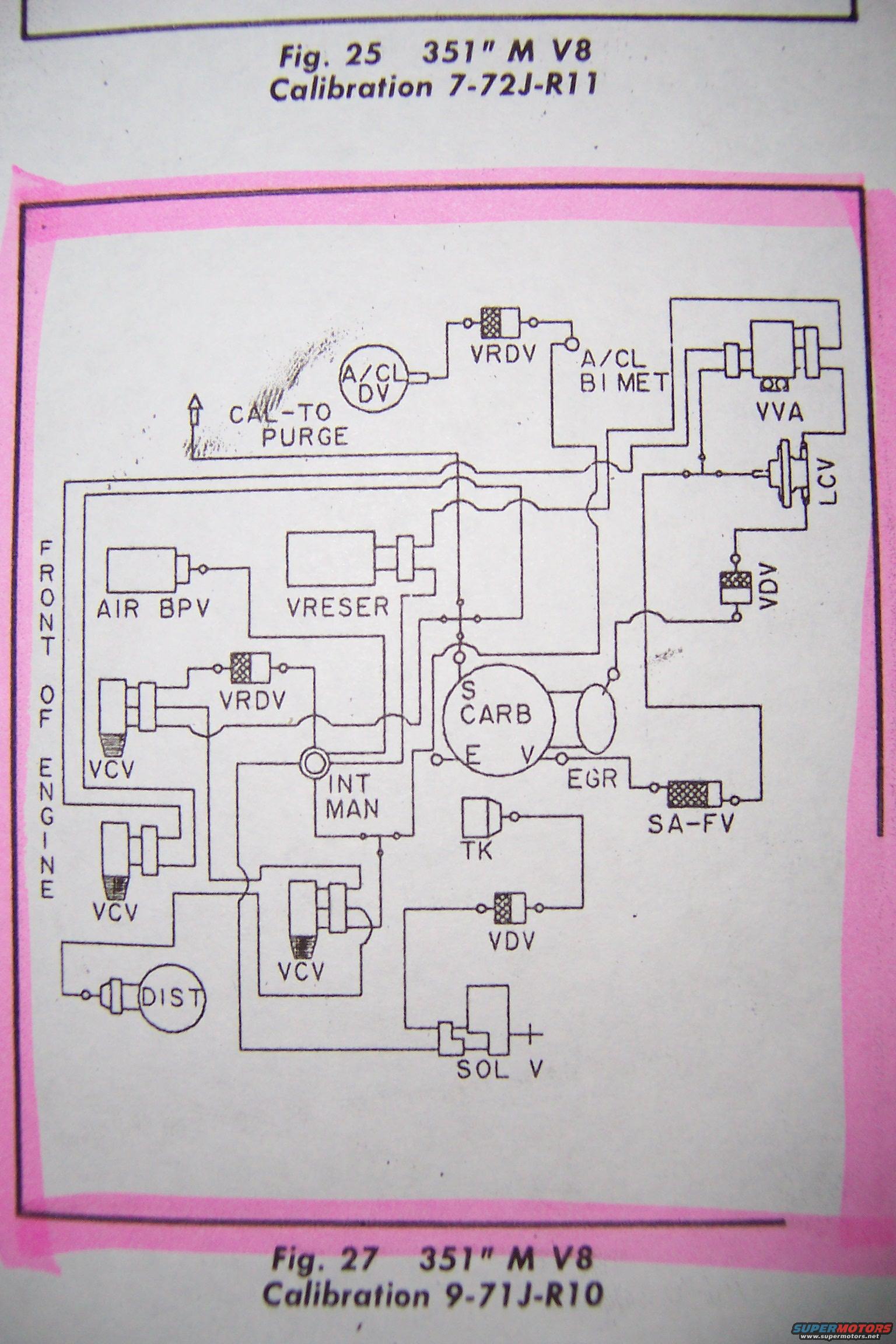
Vacuum routing schematic for a 351 M V8 (calibration 7-72J-R11) showing emission and carburetor vacuum hose connections.
Part of 1977-1979 Ford Ranchero Vacuum Routing Diagrams
This document is a scanned page from an emissions/vacuum routing reference showing a vacuum hose schematic for a Ford 351M (351") V8 engine. The page contains two figure captions: Fig. 25 identifies calibration 7-72J-R11, and Fig. 27 (the diagram highlighted in pink on this page) identifies calibration 9-71J-R10, both for the 351" M V8. The schematic, oriented with 'FRONT OF ENGINE' along the left side, traces vacuum lines between emissions components including the air cleaner delay valve (A/CL DV), air cleaner bi-metal sensor (A/CL BI MET), vacuum retard/delay valves (VRDV, VDV), vacuum check valves (VCV), vacuum vent/auxiliary valve (VVA), load control valve (LCV), air bypass valve (AIR BPV), vacuum reservoir (VRESER), spark advance fuel valve (SA-FV), EGR valve, thermal kicker (TK), solenoid valve (SOL V), distributor (DIST), carburetor (S CARB with E and V ports), intake manifold (INT MAN), and a line marked CAL-TO PURGE. A reader can use this diagram to identify the correct factory vacuum hose routing and component connections for a 351M V8 with the 9-71J-R10 (or 7-72J-R11) emissions calibration.
Is this accurate? Sign in to help verify it.
Frequently asked questions
- What engine does this vacuum diagram cover?
- The captions identify it as the 351" M V8 (351M), with Fig. 25 for calibration 7-72J-R11 and Fig. 27 for calibration 9-71J-R10.
- What emissions components are shown in the routing diagram?
- The diagram shows A/CL DV, VRDV, A/CL BI MET, VVA, LCV, AIR BPV, VRESER, VCV (multiple), VDV (two), the carburetor (S CARB with E and V ports), EGR, SA-FV, INT MAN, TK, SOL V, and DIST, plus a CAL-TO PURGE line.
- How is the diagram oriented?
- The left side of the diagram is labeled 'FRONT OF ENGINE,' so the schematic is drawn as viewed with the engine front at the left.
- Where does the EGR valve connect on this diagram?
- The EGR connection is shown at the carburetor's E port area, with a line running through the SA-FV valve.
No comments yet.