Home/
Registry/
Ford/
Bronco II/
1984-1990/
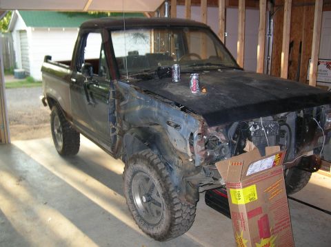
1985 Ford Bronco II/
Photo
supermotors.net/registry/media/794044
Auxiliary Cooling Fan Relay & Motor Wiring Diagram - VCM Controlled, Fuse Block

Reference · 1984-1990 Bronco IIAll 1 wiring diagrams
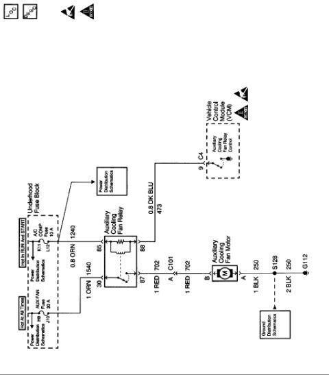
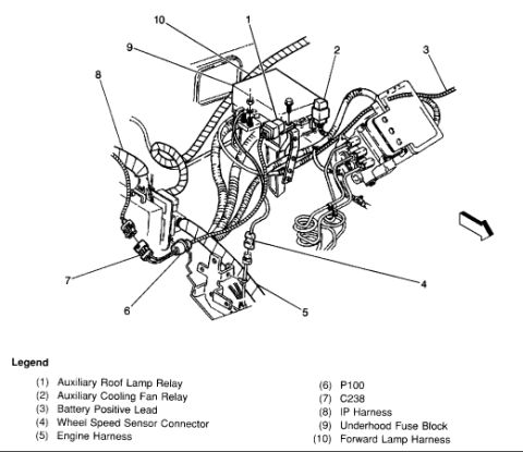
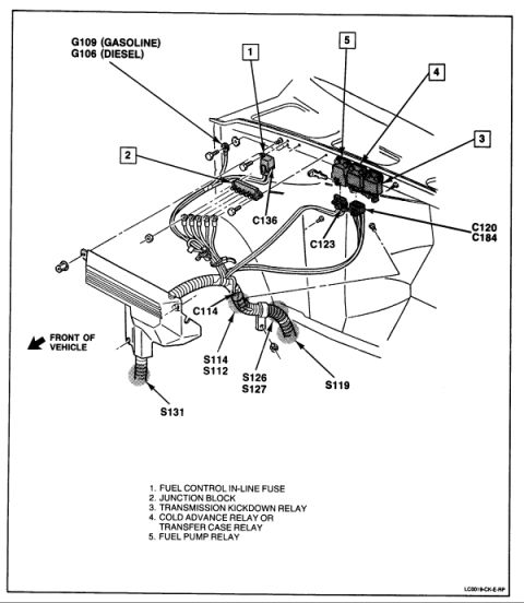
Wiring diagram of the auxiliary cooling fan relay and motor circuit with color-coded wires, circuit numbers and connector references.
Part of 1984-1990 Ford Bronco II Wiring Diagrams
This document is a single-page electrical schematic for an auxiliary (electric) engine cooling fan circuit. It shows power originating in the Underhood Fuse Block from two fuses: a 30 A AUX FAN fuse (hot at all times, positions H9/J10) and a 10 A A/C COMP fuse (hot in RUN and START, positions K11/L12). The 10 A fuse feeds the Auxiliary Cooling Fan Relay coil at terminal 85 via a 0.8 ORN wire (circuit 1240); the relay coil's other side (terminal 88) is controlled by the Vehicle Control Module (VCM) through a 0.8 DK BLU wire (circuit 473) at connector C4, pin 9 (Auxiliary Cooling Fan Relay Control). The 30 A fuse feeds relay terminal 30 via a 1 ORN wire (circuit 1540). When energized, relay terminal 87 sends power on a 1 RED wire (circuit 702) through connector C101 pin A to terminal B of the Auxiliary Cooling Fan Motor. The motor grounds through a 1 BLK wire (circuit 250) to splice S128, then a 2 BLK wire (250) to ground G112. Cross-references point to Power Distribution and Ground Distribution schematics. A reader can trace the complete fan circuit, fuse ratings, relay pinout, wire colors/gauges, circuit numbers, and connector/ground locations.
Is this accurate? Sign in to help verify it.
Frequently asked questions
- What fuse powers the auxiliary cooling fan motor?
- The AUX FAN fuse, rated 30 A, located in the Underhood Fuse Block (positions H9/J10). It is hot at all times and feeds terminal 30 of the Auxiliary Cooling Fan Relay via a 1 ORN wire, circuit 1540.
- What controls the auxiliary cooling fan relay?
- The Vehicle Control Module (VCM). Relay terminal 88 connects via a 0.8 DK BLU wire (circuit 473) to VCM connector C4, pin 9, labeled Auxiliary Cooling Fan Relay Control.
- What wire runs from the relay to the fan motor?
- A 1 RED wire, circuit 702, from relay terminal 87 through connector C101 (pin A) to terminal B of the Auxiliary Cooling Fan Motor.
- How is the auxiliary cooling fan motor grounded?
- From motor terminal A, a 1 BLK wire (circuit 250) runs to splice S128, then a 2 BLK wire (circuit 250) runs to ground G112.
- Which fuse feeds the relay coil?
- The A/C COMP fuse, 10 A (positions K11/L12), hot in RUN and START, feeding relay terminal 85 via a 0.8 ORN wire, circuit 1240.



No comments yet.