Home/
Registry/
Ford/
Bronco II/
1984-1990/
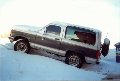
1985 Ford Bronco II/
Photo
supermotors.net/registry/media/779476
AIR Injection & EGR Valve Pipe Routing Diagram - Engine Component Locations

Reference · 1984-1990 Bronco IIAll 7 schematics
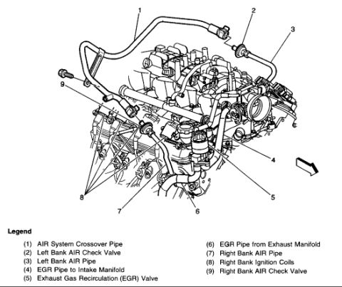
Engine schematic with numbered callouts and a legend identifying AIR system crossover pipes, EGR valve and check valves.
Part of 1984-1990 Ford Bronco II Schematics
This document is an engine top-view line illustration (schematic/exploded callout diagram) showing the secondary Air Injection Reaction (AIR) system and Exhaust Gas Recirculation (EGR) system plumbing on a V-type engine. Nine numbered callouts identify components on the engine: the AIR system crossover pipe (1) spanning the engine, the left bank AIR check valve (2) and left bank AIR pipe (3), the EGR pipe to the intake manifold (4), the EGR valve itself (5), the EGR pipe from the exhaust manifold (6), the right bank AIR pipe (7), the right bank ignition coils (8, shown as multiple coils mounted along the valve cover), and the right bank AIR check valve (9). A directional arrow at the lower right indicates orientation (likely front of vehicle). From this diagram a reader can learn the routing of the AIR crossover and bank pipes, the locations of both AIR check valves, and how the EGR valve connects between the exhaust manifold pipe and the intake manifold pipe. No part numbers, torque values, years, or vehicle model identification appear on the document itself.
Is this accurate? Sign in to help verify it.
Frequently asked questions
- Where is the EGR valve shown in this diagram?
- The Exhaust Gas Recirculation (EGR) valve is callout (5), located at the center-lower area of the engine, connected between the EGR pipe from the exhaust manifold (6) and the EGR pipe to the intake manifold (4).
- What are the numbered AIR system components in this diagram?
- (1) AIR System Crossover Pipe, (2) Left Bank AIR Check Valve, (3) Left Bank AIR Pipe, (7) Right Bank AIR Pipe, and (9) Right Bank AIR Check Valve.
- What does callout 8 identify?
- Callout (8) points to the Right Bank Ignition Coils, shown mounted in a row along the right valve cover.
- How does the EGR piping route according to the legend?
- Exhaust gas travels through the EGR pipe from the exhaust manifold (6) to the EGR valve (5), then through the EGR pipe to the intake manifold (4).


No comments yet.