Home/
Registry/
Mercury/
Cougar/
1967-1970/
1968 Mercury Cougar/
Photo
supermotors.net/registry/media/848337
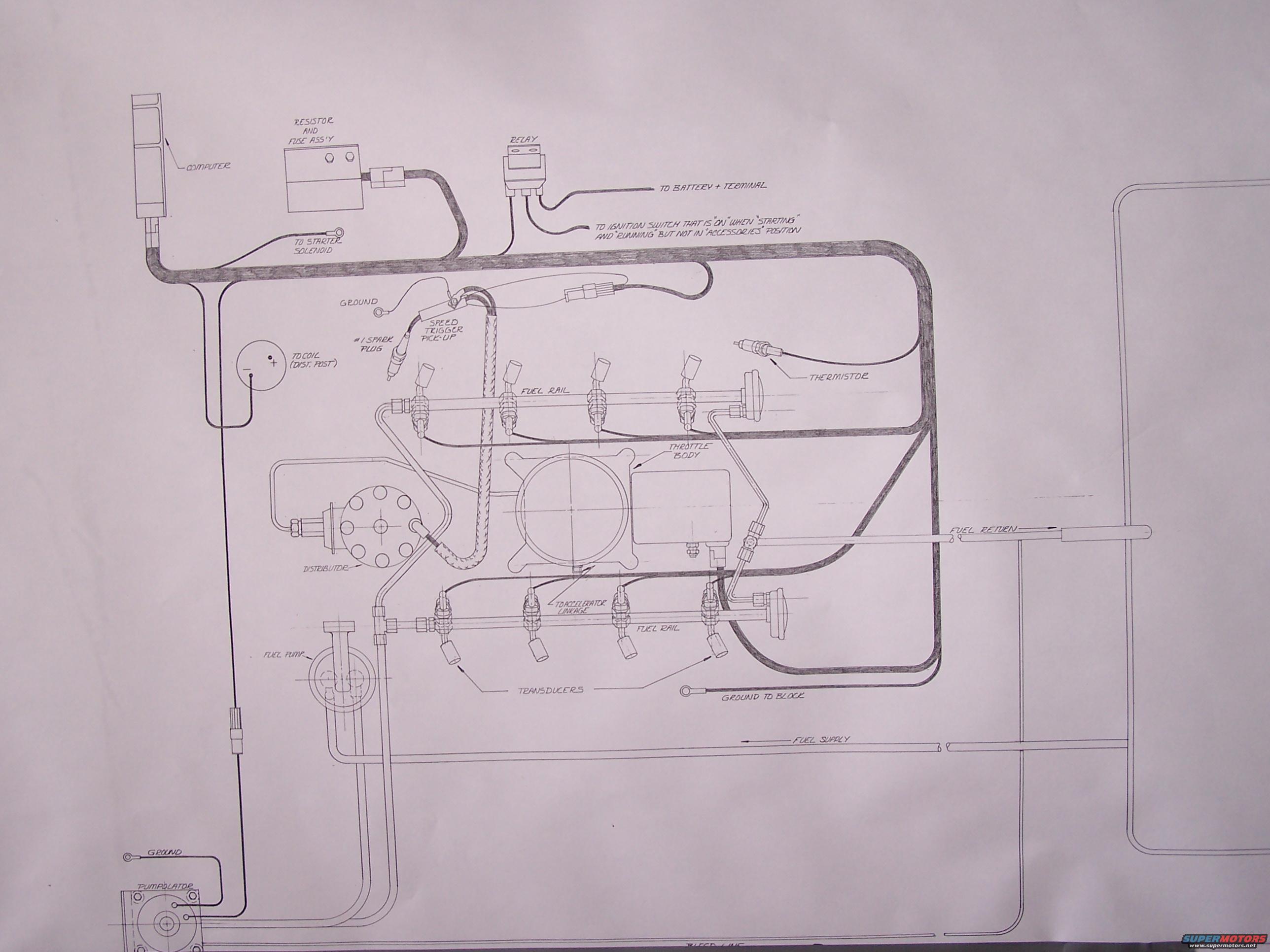
Vintage V8 Electronic Fuel Injection System Diagram - 1968 Mercury Cougar 428
Reference · 1967-1970 CougarAll 2 vacuum routing diagrams
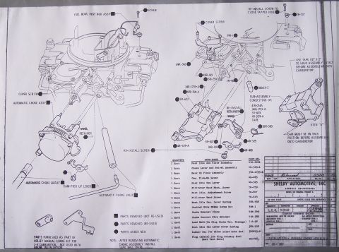
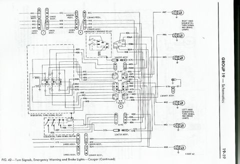
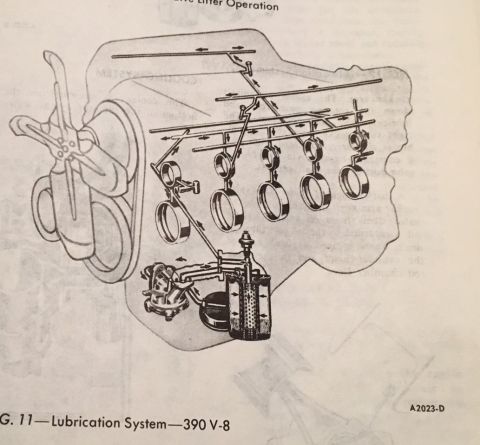
Vacuum and fuel-line routing diagram for a fuel-injection setup, showing throttle body, injectors and color-coded hose paths.
Part of 1967-1970 Mercury Cougar Vacuum Routing Diagrams
This document is a large hand-drawn schematic/installation diagram of an early electronic fuel injection (EFI) system for a V8 engine. It shows the complete layout of the system's electrical and fuel plumbing components: a COMPUTER (control unit), a RESISTOR AND FUSE ASSEMBLY, and a RELAY with connections labeled to the battery positive terminal, to the starter solenoid, and to an ignition switch circuit that is hot in "STARTING" and "RUNNING" but not in the "ACCESSORIES" position. Ignition-related items include a SPEED TRIGGER PICK-UP on the #1 spark plug wire, a connection TO COIL (DIST. POST), and the DISTRIBUTOR. The fuel system side shows two FUEL RAILS (one per cylinder bank) with injectors, a central THROTTLE BODY with an arrow to the accelerator linkage, a THERMISTOR (temperature sensor), TRANSDUCERS on the injectors/rails, a FUEL PUMP, and a device labeled PUMPULATOR at lower left, plus FUEL SUPPLY, FUEL RETURN, and BLEED LINE routing to the tank at right. Ground points (GROUND, GROUND TO BLOCK) are indicated. A reader can learn how each component of this vintage EFI system is wired and plumbed relative to the engine. The drawing is undated and does not state a vehicle model.
Is this accurate? Sign in to help verify it.
Frequently asked questions
- What ignition switch circuit should the EFI relay be connected to?
- The diagram specifies connection to an ignition switch terminal that is "ON" when "STARTING" and "RUNNING" but not in the "ACCESSORIES" position.
- Where does the speed trigger pick-up connect?
- The speed trigger pick-up is shown clamped on the #1 spark plug wire, with a separate ground connection.
- What fuel lines are shown in the diagram?
- The diagram shows a fuel supply line, a fuel return line, and a bleed line, along with two fuel rails, a fuel pump, and a component labeled 'Pumpulator'.
- What sensors and electrical components are part of this fuel injection system?
- The diagram shows a computer, a resistor and fuse assembly, a relay, a thermistor, a speed trigger pick-up, and transducers on the fuel rails/injectors.
- How is the system grounded?
- Multiple ground points are shown: a ground for the speed trigger pick-up, a 'ground to block' lead near the transducers, and a ground at the Pumpulator.
No comments yet.