Home/
Registry/
Mercury/
Cougar/
1967-1970/
1968 Mercury Cougar/
Photo
supermotors.net/registry/media/848336
Shelby American Blueprint S8MS 9C501-A Timing Gear & Hub, Lucas Mark II Fuel Inj
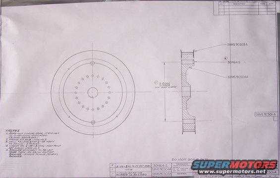
Engineering blueprint with dimensioned front and section views of a pulley/flange, including notes, part numbers, and a title block.
This is a scan of an original Shelby American, Inc. engineering blueprint (drawing number S8MS 9C501-A) titled "Timing Gear and Hub Assembly, Fuel Inj," drawn for the Lucas Mark II fuel injection model. Dated May 1967 (drafted 5-9-67 by D.D. Pushak, engineered by J. Dunn 5-16-67, approved 5-17-67), it shows a front view and a cross-section of a toothed timing gear and hub assembly at 2x full size. The parts list specifies one timing gear made of US Rubber No. 40 L 050 (part S8MS 9C503A), one hub (S8MS 9C504A), and two 1/4-28 x 3/8 flat-point set screws (301464-S). Assembly notes instruct boring the timing gear to 3.5010-3.5013 in. diameter, press-fitting the hub, drilling #3 (.213) and tapping 1/4-28 in two places, inserting the set screws, and statically balancing the assembly to within.01 oz/in in a single plane. A dimension calls out a 3.5000/3.5005 diameter bolt circle. Standard tolerances (decimals ±.01/±.005, fractions ±1/16, angles ±15') are listed, and the drawing is marked "Do Not Scale Dwg." The Shelby American address of 6501 West Imperial Hwy., Los Angeles, California appears in the title block.
Is this accurate? Sign in to help verify it.
Frequently asked questions
- What is drawing S8MS 9C501-A?
- It is a Shelby American, Inc. blueprint for a Timing Gear and Hub Assembly for fuel injection, drawn at 2x full size for the Lucas Mark II fuel injection model, dated May 1967.
- What parts make up the timing gear and hub assembly?
- One timing gear of US Rubber No. 40 L 050 (S8MS 9C503A), one hub (S8MS 9C504A), and two 1/4-28 x 3/8 long flat-point set screws (301464-S).
- What bore dimension is specified for the timing gear?
- Note 1 says to bore out the timing gear to the dimension indicated, 3.5010-3.5013 diameter, and the hub press-fits into it. A 3.5000/3.5005 diameter bolt circle is dimensioned on the section view.
- What is the balance requirement for the assembly?
- Note 5 requires the assembly to be no more than.01 oz/in out of balance, single plane (static) balance.
- Who drew and approved this blueprint?
- Draftsman D.D. Pushak dated 5-9-67, engineer J. Dunn 5-16-67, with designer and approval signatures dated 5-16-67 and 5-17-67.
Comments
More from this build
No comments yet.