Home/
Registry/
Shelby/
GT500/
1967-1970/
1968 Shelby GT500/
Photo
supermotors.net/registry/media/849570
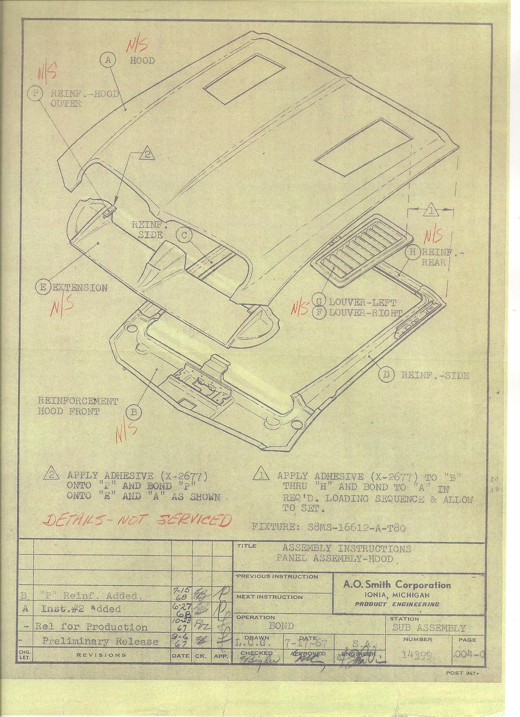
1968 Shelby GT500 Hood Panel Assembly Instructions - A.O. Smith Exploded Diagram
Reference · 1967-1970 GT500All 3 exploded parts diagrams


A.O. Smith hood panel assembly drawing with lettered component callouts and bonding instructions.
Part of 1967-1970 Shelby GT500 Exploded Parts Diagrams
This is an original A.O. Smith Corporation (Ionia, Michigan, Product Engineering) factory assembly instruction sheet, number 14399, page.004-0, titled "Assembly Instructions: Panel Assembly-Hood." It shows an exploded isometric drawing of a fiberglass hood assembly with lettered callouts: (A) Hood, (B) Reinforcement Hood Front, (C) Reinf Side, (D) Reinf.-Side, (E) Extension, (F) Louver-Right, (G) Louver-Left, (H) Reinf.-Rear, and (P) Reinf.-Hood Outer. Bonding instructions specify applying adhesive X-2677 to components B through H and bonding them to hood panel A in the required loading sequence, and applying X-2677 to bond reinforcement P onto E and A. The bonding fixture is identified as S8MS-16612-A-T80. The operation is "Bond" at the "Sub Assembly" station. Red handwritten annotations mark most components "N/S" with the note "DETAILS: NOT SERVICED." The revision block documents Preliminary Release 9-6-67, Release for Production 10-23-67, Instruction #2 added 6-27-68, and "P" reinforcement added 7-15-68; drawn by L.C.G. on 7-17-67. Readers learn the component makeup of the hood, the bonding adhesive and fixture used, and the production revision history of this Shelby-era part.
Is this accurate? Sign in to help verify it.
Frequently asked questions
- What adhesive was used to bond the hood reinforcements?
- Adhesive X-2677 was applied to components "B" thru "H" and bonded to hood panel "A" in the required loading sequence, then allowed to set. X-2677 was also used to bond the outer hood reinforcement "P" onto "E" and "A."
- What components make up this hood panel assembly?
- The exploded view shows: (A) Hood, (B) Reinforcement Hood Front, (C) Reinf Side, (D) Reinf.-Side, (E) Extension, (F) Louver-Right, (G) Louver-Left, (H) Reinf.-Rear, and (P) Reinf.-Hood Outer.
- What fixture was used for the hood bonding operation?
- Fixture S8MS-16612-A-T80, used at the Sub Assembly station for the Bond operation.
- Who produced this assembly instruction and when?
- A.O. Smith Corporation, Product Engineering, Ionia, Michigan. It was drawn by L.C.G. on 7-17-67, preliminarily released 9-6-67, released for production 10-23-67, with revisions added 6-27-68 and 7-15-68.
- Were the individual hood components available as service parts?
- Per the red handwritten annotations, most components are marked "N/S" with the note "DETAILS - NOT SERVICED," indicating the individual detail parts were not serviced separately.

No comments yet.