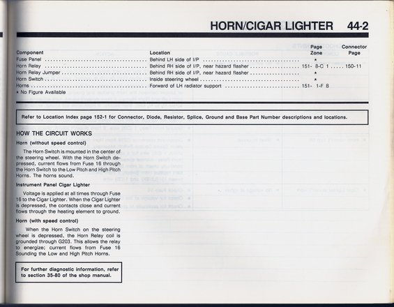
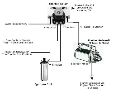
Diagram details the horn and cigar lighter circuit, including component locations and how the system works.
T ~ - + i HORN/CIGAR LIGHTER 44-2 _1 .2 i Page Connector mponent Location Zone Page se Panel ..................................... Behind LH side of UP ................................... a 3m Relay ....... 7 ............................. Behind RH side of VP, near hazard flasher... .. . . . . . . . .. .. . . 151~ 8-0 1 ..... 150-11 l lixarn Relay Jumper ............................... Behind RH side of VP, near hazard flasher .................. at La Switch ..................................... Inside steering wheel .................................... * rns ...... _ ..... ' ............................... Forward of LH radiator support ........................... 151- 1F 8 No Figure Available L 'L 5 Refer to Location Index page 152- 1 for Connector, Diode, Resistor, Splice, Ground and Base Part Number descriptions and locations. Ll wow THE CIRCUIT WORKS Lforn (without speed control) _ The Horn Switch Is mounted in the center of mi e steering wheel. With the Horn Switch de- ressed current flows from Fuse 16 through figs Horn Switch to the Low Pitch and High Pitch I orns The horns sound. Lstrument Panel Cigar Lighter . Voltage' Is applied at all times through Fuse 6 to the Cigar Lighter. When the Cigar Lighter i depressed, the contacts close and current ows through the heating element to ground. Liorn (with speed control) 3. When the Horn Switch on the steering L heel is depressed, the Horn Relay coil is (#:grounded through 6203. This allows the relay li energize; current flows from Fuse 16 LoundIng the Low and High Pitch Horns. I L For further diagnostic information, refer L to section 35-80 of the shop manual. , I
Comments
More from this build


No comments yet.