Home/
Registry/
Ford/
Bronco/
1992-1996/
“pukin' dogII”/
Photo
supermotors.net/registry/media/877787
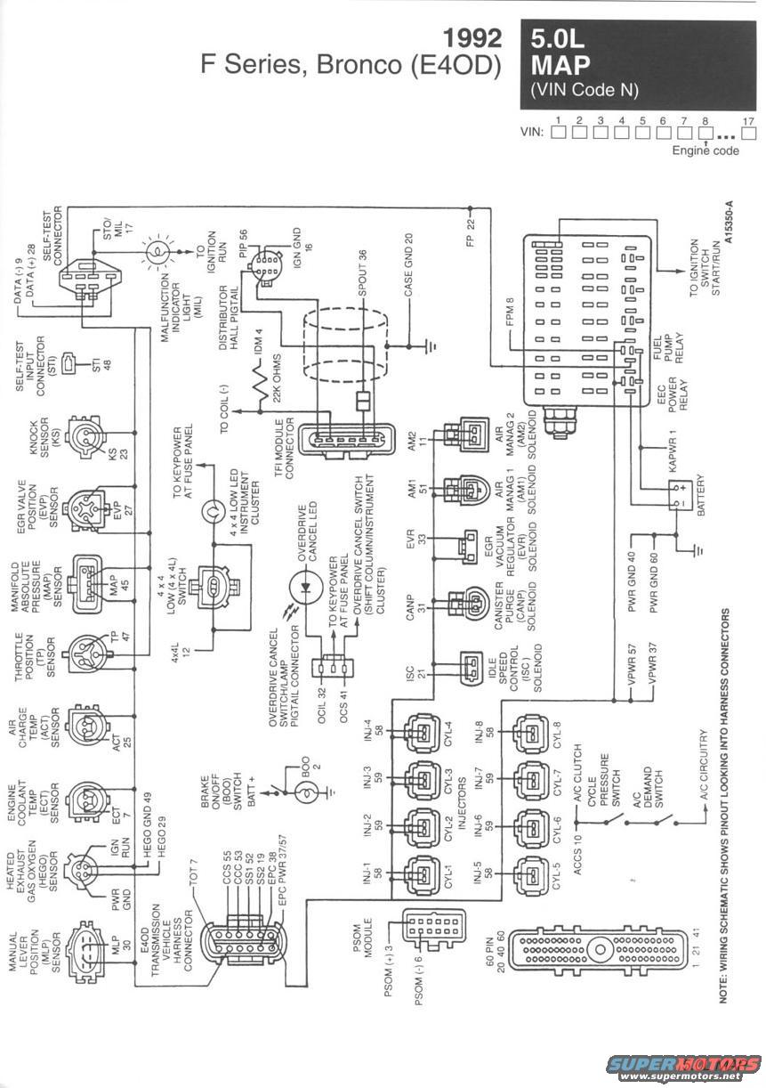
1992 Ford F-Series & Bronco 5.0L E4OD EEC-IV Wiring Diagram - PCM Pinout (MAP)
Reference · 1992-1996 BroncoAll 411 wiring diagrams
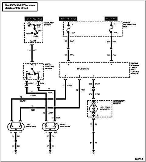
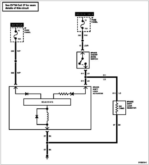
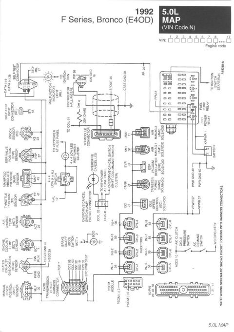













Full electrical wiring diagram for 1992 Ford F-Series/Bronco 5.0L showing connectors, sensors and circuit routing.
Part of 1992-1996 Ford Bronco Wiring Diagrams
This document is a 1992 Ford F-Series and Bronco (E4OD transmission) EEC-IV wiring schematic for the 5.0L MAP engine (VIN engine code N, 8th VIN position). It is Ford diagram A15350-A and shows the 60-pin PCM harness connector pinout (viewed looking into the harness connectors) with every sensor, actuator, and circuit assignment. Sensors shown with their PCM pin numbers include the knock sensor (KS 23), EGR valve position (EVP 27), MAP (45), throttle position (TP 47), air charge temp (ACT 25), engine coolant temp (ECT 7), heated oxygen sensor (HEGO 29/GND 49), and manual lever position sensor (MLP 30). Actuators include the air management solenoids (AM1 51, AM2 11), EGR vacuum regulator (EVR 33), canister purge (CANP 31), and idle speed control (ISC 21). The diagram also covers the self-test connector (DATA 9/28, STO/MIL 17), TFI module and distributor Hall pigtail (PIP 56, IDM 4, SPOUT 36), fuel pump and EEC power relays, all eight fuel injectors (pins 58/59 paired by bank), the E4OD transmission harness connector (TOT 7, CCS 55, OCC 53, SS1 52, SS2 19, EPC 38), 4x4 low switch, overdrive cancel switch/LED, brake on/off switch (BOO 2), A/C clutch cycle switch (ACCS 10), and PSOM speed sensor wiring.
This document covers 1992, which may differ from this 1996 Ford Bronco.
Is this accurate? Sign in to help verify it.
Frequently asked questions
- What engine and vehicles does this wiring diagram cover?
- It covers the 1992 Ford F-Series and Bronco with the E4OD transmission and the 5.0L MAP engine, VIN engine code N (8th VIN character).
- What PCM pins do the fuel injectors use on the 1992 5.0L?
- Injectors 1, 4, 5, and 8 connect to pin 58, and injectors 2, 3, 6, and 7 connect to pin 59.
- Which PCM pins are used for the E4OD transmission connector?
- TOT 7, CCS 55, OCC 53, SS1 52, SS2 19, EPC 38, and EPC power on pins 37/57.
- What pins are the self-test (diagnostic) connector wired to?
- DATA (-) to pin 9, DATA (+) to pin 28, and STO/MIL to pin 17, with the MIL fed from ignition run power.
- Which pins provide PCM power and ground?
- KAPWR is pin 1, VPWR is pins 37 and 57, and power grounds are pins 40 and 60; case ground is pin 20.






No comments yet.