Home/
Registry/
Ford/
F-100/
1967-1972/
1967 Ford F-100/
Photo
supermotors.net/registry/media/992320
Ford F-100 Disc Brake Caliper Bracket - SolidWorks CAD Model & Drawing
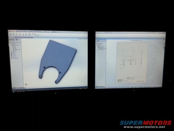
Photograph of dual monitors showing a SolidWorks bracket model alongside its dimensioned engineering drawing.
Part of 1967-1972 Ford F-100 Blueprints
This is a photograph of a dual-monitor computer setup running SolidWorks, documenting the design of a custom part labeled "F100 Caliper Bracket." The left monitor shows the 3D solid model of the bracket, a flat plate with a large semicircular cutout (to clear an axle or hub) and two lower ears with mounting holes, along with the SolidWorks feature tree listing features such as fillets, a chamfer, a hole pattern, and a fillet pattern. The right monitor shows the corresponding 2D engineering drawing (Sheet1) with front and side views and key dimensions: a 3.56 spacing dimension, Ø.39±.01 mounting holes, an R1.75 center radius, a 2.00 dimension, 4X R.20 fillets, and 2X R2.34 radii, at a 1:4 sheet scale in inch units (IPS). A reader can learn the general geometry and critical hole dimensions of this home-designed brake caliper mounting bracket intended for a Ford F-100, though the smaller title-block notes are not legible in the photo. It serves as design documentation for a disc brake caliper bracket fabrication project.
Is this accurate? Sign in to help verify it.
Frequently asked questions
- What part is being designed in this CAD screenshot?
- An "F100 Caliper Bracket", a flat brake caliper mounting bracket modeled and detailed in SolidWorks, shown as both a 3D model and a 2D drawing.
- What are the mounting hole size and spacing shown on the drawing?
- The drawing calls out Ø.39±.01 holes with a 3.56 spacing dimension and a 2.00 offset dimension.
- What radii are specified on the bracket?
- An R1.75 central radius, 4X R.20 fillets, and 2X R2.34 outer radii.
- What software and units were used?
- SolidWorks (Premium), with the drawing in IPS (inch) units at a 1:4 sheet scale.
Comments
More from this build
No comments yet.