Home/
Registry/
Ford/
F-100/
1967-1972/
1967 Ford F-100/
Photo
supermotors.net/registry/media/992321
Ford F-100 Custom Brake Caliper Bracket - SolidWorks CAD Design Screenshot
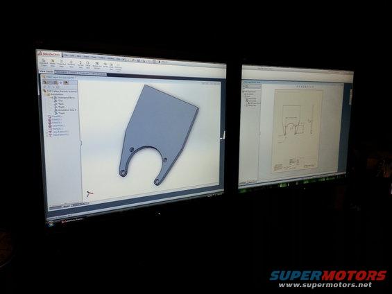
Photograph of dual monitors showing a SolidWorks bracket model alongside its dimensioned engineering drawing.
Part of 1967-1972 Ford F-100 Blueprints
This is a photograph of a dual-monitor computer workstation running SolidWorks Premium 2013, capturing the design process for a custom part labeled "F100 Caliper Bracket." The left monitor shows the 3D part file (F100 Caliper Bracket.SLDPRT) with its feature tree visible, including annotations, reference planes (Plane20, Plane21), fillets (Fillet12, Fillet13), a chamfer (Chamfer4), a hole pattern (Hole Pattern3), and a fillet pattern (Fillet Pattern3). The modeled part is a flat plate bracket with a large semicircular cutout, two lower arm extensions each with a mounting hole, and additional holes flanking the cutout, consistent with a disc brake caliper mounting bracket. The right monitor shows the corresponding 2D engineering drawing (F100 Caliper Bracket - Sheet1) with dimensioned front and edge views and a title block, though the individual dimension values are too small to read in the photo. A reader learns that the owner was CAD-designing a custom caliper bracket for their F-100, presumably for a disc brake conversion, but no actual dimensions, materials, or part numbers can be extracted from this image.
Is this accurate? Sign in to help verify it.
Frequently asked questions
- What part is being designed in this document?
- A part named "F100 Caliper Bracket", a flat bracket with a large semicircular cutout, two lower arms with holes, and additional mounting holes, modeled as F100 Caliper Bracket.SLDPRT.
- What software was used to design the F100 caliper bracket?
- SolidWorks Premium 2013, shown running the 3D part model on one monitor and the 2D drawing (F100 Caliper Bracket - Sheet1) on the other.
- What features are in the SolidWorks feature tree for this bracket?
- Annotations (Top, Back, Right, Front, Annotation View 4), Plane20, Fillet12, Fillet13, Chamfer4, Plane21, Hole Pattern3, and Fillet Pattern3.
- Can actual dimensions of the bracket be read from this image?
- No. A dimensioned 2D drawing is visible on the right monitor, but the dimension values and title block are too small and blurry to read.
Comments
More from this build
No comments yet.