![Original battery terminals
IF THE IMAGE IS TOO SMALL, click it.
The top 2 are the Left battery; all the others show the Right battery. Probes are either on the CLAMPS (for the higher readings, because the engine is idling & the alternator is the voltage source), or on the POSTS (for the lower readings, because of the resistance across the post-to-clamp connections).
While I had the DMM out for other jobs, I checked the battery voltage at idle, and found 3 of the abused terminals were OK (no voltage drop). But the Right positive (4th pic) had about 2 volts drop from the alternator to the battery post, so I removed it. The clamp bolt broke instantly (5th pic), which wasn't really surprising. After cleaning the mating surfaces (6th & 7th pics), bending the Lead clamp slightly, & installing a stainless bolt with spacer nut (8th pic), the battery is now able to receive & deliver full voltage (8th pic).
But I still plan to replace all 4 terminals.
[url=https://www.supermotors.net/registry/media/1158308_1][img]https://www.supermotors.net/getfile/1158308/thumbnail/20200330_001404.jpg[/img][/url] . [url=https://www.supermotors.net/registry/media/1158444_1][img]https://www.supermotors.net/getfile/1158444/thumbnail/20200330_163102.jpg[/img][/url] . [url=https://www.supermotors.net/registry/2742/69178-4][img]https://www.supermotors.net/getfile/723279/thumbnail/07done.jpg[/img][/url]
Cleaning down to shiny metal (7th pic) is good maintenance for ANY exposed connection like the battery terminals & most ground ring terminals, or high-current case-grounded device (like a starter or alternator mount).
[url=https://www.supermotors.net/registry/media/944780][img]https://www.supermotors.net/getfile/944780/thumbnail/altl8.jpg[/img][/url] . [url=https://www.supermotors.net/registry/media/825375][img]https://www.supermotors.net/getfile/825375/thumbnail/alternatormountboss.jpg[/img][/url] . [url=https://www.supermotors.net/registry/media/1055206][img]https://www.supermotors.net/getfile/1055206/thumbnail/06bracket01.jpg[/img][/url] . [url=https://www.supermotors.net/registry/media/955475][img]https://www.supermotors.net/getfile/955475/thumbnail/26winchrelays.jpg[/img][/url] . [url=https://www.supermotors.net/registry/media/1172142][img]https://www.supermotors.net/getfile/1172142/thumbnail/battstrays24.jpg[/img][/url]
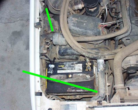
Don't use dielectric grease; use electrical grease (green pointer) to put a light film on the polished bosses, and the main output terminal. It will also help keep water out of the other connectors, but it only takes a little.
[url=https://www.fcsdchemicalsandlubricants.com/products/greases/productdetails?id=17]Electrical Grease XG-12 (F8AZ-19G208-AA)
[img]https://www.fcsdchemicalsandlubricants.com/images/products/6dd8cd88-9164-45c3-b4b4-2bcf20d149ba..jpg[/img][/url]
To bypass the voltage regulator and force the alternator to its peak output (at the current RPM), ground the screw indicated by the small black pointer at the far L of the pic. If the output does NOT spike, the alternator is probably bad. Don't keep it grounded any longer than it takes to get a voltage or current reading because the alt will overheat rapidly, especially at hi rev, and any electrical components (including the battery) can be damaged.
[url=https://www.supermotors.net/registry/media/825495][img]https://www.supermotors.net/getfile/825495/thumbnail/cont6.jpg[/img][/url] . [url=https://www.supermotors.net/registry/media/723349][img]https://www.supermotors.net/getfile/723349/thumbnail/alternator-130a.jpg[/img][/url] . [url=https://www.supermotors.net/registry/media/843907][img]https://www.supermotors.net/getfile/843907/thumbnail/alternator3gvr.jpg[/img][/url]
DO NOT USE [url=https://www.fcsdchemicalsandlubricants.com/products/greases/productdetails.aspx?id=25]Silicone Brake Caliper Grease And Dielectric Compound XG-3A (D7AZ-19A331-A)[/url] on electrical connections or terminals.
[url=http://www.fcsdchemicalsandlubricants.com/Main/product.asp?product=Silicone Brake Caliper Grease and Dielectric Compound&category=Greases]
[img]https://www.fcsdchemicalsandlubricants.com/images/products/XG3A.jpg[/img][/url]
___________________________________________________
"Grounding" is commonly misunderstood...
When electricity first became publicly available (when Edison & Tesla were fighting over DC vs. AC), Copper wire was very expensive. So rather than run 2 wires everywhere, Tesla realized he could run a "hot" wire, and then use the ground (the actual dirt of the Earth) as the return circuit path. (He also thought he could use the ionosphere as the hot side, but he never got that to work.) Inside a house, there still had to be 2 wires, but one of them went "to the ground" via a Copper rod driven into the dirt outside the house. That became known as "the ground wire". When vehicles acquired electric circuits (AFAIK, the first on any Ford was the electric horn, which Ford always numbers as circuit #1), it was equally-efficient to use the metal chassis of the vehicle as one of the main electrical pathways, to reduce the amount of wire needed. And the term "ground" was carried over into that arena. Chassis grounding worked reasonably-well until alternators got up into the ~100A range (in the 80s) and vehicle wiring harnesses began to exceed the weight of the drivetrain (AFAIK, the first to cross that line was the '92 Lincoln Continental V6). Since then, more circuits are networked through high-speed data bus lines via communication modules so that you don't need a discrete wire running from one end of the vehicle to the other & another coming back to turn on a taillight, and confirm that the bulb isn't burnt out.
But as a result, the chassis/body ground is no longer sufficient to provide a reliable circuit path without introducing a lot of background noise (RFI) into those minuscule high-frequency data signals. So the trend for a couple of decades now has been to run actual Copper return wires so that far less current flows through the chassis steel. (House wiring standards added a return "neutral" wire decades before that.)
So by definition, if you're using a wire to return to the battery, you're not "grounding" that circuit - you're wiring it. And wiring it is a good idea when you're dealing with rusty 40- to 50-year-old body & frame steel. The catch is that the return wiring has to be AT LEAST as large as ALL the power wiring that it serves - IOW, very big like the alternator output wire, the starter wire, the winch wiring, and the ignition switch battery-supply wires. None of it needs to be bigger than the battery cables because you can't ever get more current flowing than the battery can put out (roughly whatever its CA rating is).
So if you want to be sure you have a good return path throughout any vehicle, just extend the battery (-) cable all the way to the trailer connector. Obviously, you can't run a cable that big into the trailer connector or anything else - you have to splice onto it to branch off with smaller black wire (or whatever color the particular circuit uses for "ground"). That's why I refer to that as a "trunk ground" system - the main return wire is like a big tree trunk, with the variously-sized smaller branches shooting out to hit each point on the vehicle that needs an exceptionally-reliable return (generally: the high-current devices; and those that require low RFI noise, like audio amplifiers).
Fortunately, those splices DON'T need to be insulated - they can be left showing bare metal. Copper & solder don't corrode very quickly in air, or even in common rainwater. Mainly just at the battery where acid leaks out. Road salt will eventually cause some corrosion, but probably not enough to matter within the remaining lifespan of even the best-maintained antiques.
And the body & frame should still be GROUNDED at a few points, just to reduce galvanic corrosion, and to serve the very-low-current chassis-grounded loads like taillights & fuel level senders.](https://www.supermotors.net/getfile/1157161/fullsize/voltage.jpg)
Original battery terminals
IF THE IMAGE IS TOO SMALL, click it.
The top 2 are the Left battery; all the others show the Right battery. Probes are either on the CLAMPS (for the higher readings, because the engine is idling & the alternator is the voltage source), or on the POSTS (for the lower readings, because of the resistance across the post-to-clamp connections).
While I had the DMM out for other jobs, I checked the battery voltage at idle, and found 3 of the abused terminals were OK (no voltage drop). But the Right positive (4th pic) had about 2 volts drop from the alternator to the battery post, so I removed it. The clamp bolt broke instantly (5th pic), which wasn't really surprising. After cleaning the mating surfaces (6th & 7th pics), bending the Lead clamp slightly, & installing a stainless bolt with spacer nut (8th pic), the battery is now able to receive & deliver full voltage (8th pic).
But I still plan to replace all 4 terminals. .
.  .
. 
Cleaning down to shiny metal (7th pic) is good maintenance for ANY exposed connection like the battery terminals & most ground ring terminals, or high-current case-grounded device (like a starter or alternator mount). .
.  .
.  .
.  .
. 
Don't use dielectric grease; use electrical grease (green pointer) to put a light film on the polished bosses, and the main output terminal. It will also help keep water out of the other connectors, but it only takes a little.
Electrical Grease XG-12 (F8AZ-19G208-AA)
To bypass the voltage regulator and force the alternator to its peak output (at the current RPM), ground the screw indicated by the small black pointer at the far L of the pic. If the output does NOT spike, the alternator is probably bad. Don't keep it grounded any longer than it takes to get a voltage or current reading because the alt will overheat rapidly, especially at hi rev, and any electrical components (including the battery) can be damaged. .
.  .
. 
DO NOT USE Silicone Brake Caliper Grease And Dielectric Compound XG-3A (D7AZ-19A331-A) on electrical connections or terminals.
___________________________________________________
"Grounding" is commonly misunderstood...
When electricity first became publicly available (when Edison & Tesla were fighting over DC vs. AC), Copper wire was very expensive. So rather than run 2 wires everywhere, Tesla realized he could run a "hot" wire, and then use the ground (the actual dirt of the Earth) as the return circuit path. (He also thought he could use the ionosphere as the hot side, but he never got that to work.) Inside a house, there still had to be 2 wires, but one of them went "to the ground" via a Copper rod driven into the dirt outside the house. That became known as "the ground wire". When vehicles acquired electric circuits (AFAIK, the first on any Ford was the electric horn, which Ford always numbers as circuit #1), it was equally-efficient to use the metal chassis of the vehicle as one of the main electrical pathways, to reduce the amount of wire needed. And the term "ground" was carried over into that arena. Chassis grounding worked reasonably-well until alternators got up into the ~100A range (in the 80s) and vehicle wiring harnesses began to exceed the weight of the drivetrain (AFAIK, the first to cross that line was the '92 Lincoln Continental V6). Since then, more circuits are networked through high-speed data bus lines via communication modules so that you don't need a discrete wire running from one end of the vehicle to the other & another coming back to turn on a taillight, and confirm that the bulb isn't burnt out.
But as a result, the chassis/body ground is no longer sufficient to provide a reliable circuit path without introducing a lot of background noise (RFI) into those minuscule high-frequency data signals. So the trend for a couple of decades now has been to run actual Copper return wires so that far less current flows through the chassis steel. (House wiring standards added a return "neutral" wire decades before that.)
So by definition, if you're using a wire to return to the battery, you're not "grounding" that circuit - you're wiring it. And wiring it is a good idea when you're dealing with rusty 40- to 50-year-old body & frame steel. The catch is that the return wiring has to be AT LEAST as large as ALL the power wiring that it serves - IOW, very big like the alternator output wire, the starter wire, the winch wiring, and the ignition switch battery-supply wires. None of it needs to be bigger than the battery cables because you can't ever get more current flowing than the battery can put out (roughly whatever its CA rating is).
So if you want to be sure you have a good return path throughout any vehicle, just extend the battery (-) cable all the way to the trailer connector. Obviously, you can't run a cable that big into the trailer connector or anything else - you have to splice onto it to branch off with smaller black wire (or whatever color the particular circuit uses for "ground"). That's why I refer to that as a "trunk ground" system - the main return wire is like a big tree trunk, with the variously-sized smaller branches shooting out to hit each point on the vehicle that needs an exceptionally-reliable return (generally: the high-current devices; and those that require low RFI noise, like audio amplifiers).
Fortunately, those splices DON'T need to be insulated - they can be left showing bare metal. Copper & solder don't corrode very quickly in air, or even in common rainwater. Mainly just at the battery where acid leaks out. Road salt will eventually cause some corrosion, but probably not enough to matter within the remaining lifespan of even the best-maintained antiques.
And the body & frame should still be GROUNDED at a few points, just to reduce galvanic corrosion, and to serve the very-low-current chassis-grounded loads like taillights & fuel level senders.
Comments
More from this build


No comments yet.