"TRICKS OF THE TRADE"
Many speed control concerns can be easily resolved by using the following "Tricks of the Trade" diagnostics. If a concern cannot be resolved, refer to the shop manual, Section 37-05 for additional component testing.
VERIFY CUSTOMER CONCERN
Before performing speed control diagnosis, the customer concern should be verfied. Occasionally, the customer does not completely understand operation of the speed control system. If this is the case, the customer should be referred to the Owner Guide for complete speed control operating instructions.
Most misunderstanding involves operation of the RESUME feature. RESUME should be used to return to a previously set speed after speed control operation has been interrupted. The RESUME feature will not operate if the vehicle speed has been lowered through use of the COAST button. The release of the COAST button sets the new lower speed into the control memory. Also, RESUMEwill not work if the vehicle speed is below the minimum speed control operating speed of about 30 mph (48 km/h).
The RESUME function for the Stand-Alone Speed Control System may not activate with a momentary tap of the RESUME button. The RESUME button must be held down for a short time to make sure of engagement.
Speed drops of more than 1 or 2 mph may occur while in speed control operation on grades or under other load conditions. This is especially true on vehicles that are equipped with automatic overdrive transmissions or with manual 5 speed transmissions. These speed drops are due to limited engine power available in the overdrive (or the highest gear of a manual transmission) mode of operation. Under heavy load conditions, such as hilly or mountainous areas or during trailer tow, the vehicle speed may drop even more. When speed drops of 10 - 13 mph (16 - 21 km/h) occur the speed control system will, by design, automatically disengage.
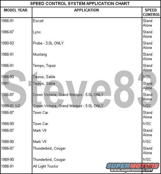
SYSTEMS
The speed control system obtains vehicle speed information from the vehicle speed sensor. In most cars and trucks the sensor is mounted on the transmission or in-line with the speedometer cable. The sensor is driven from gearing in the transmission. On 1986-90 Lincoln Town Car, Crown Victoria, Grand Marquis and Mark VII vehicles the speed signal comes from a speed sensor located in the Electronic Instrument Cluster. If the speedometer system is erratic or inoperative, it must be serviced before the speed control system is evaluated.
The speed control system also interacts with the brake system, and with the clutch system on manual transmission vehicles. Speed control requires electrical continuity through the stoplamps (and clutch switch on manual transmission vehicles) in order to operate. Proper stoplamp operation is required if the system is to disengage with brakes. Proper clutch switch operation is also required on manual transmission vehicles if the system is to disengage with clutch pedal actuation. Stoplamp and clutch switch circuit diagnosis is detailed in Section 37-05 of the appropriate Shop Manual.
NOTE: SPEED CONTROL WILL NOT DISENGAGE IF THE GEARS ARE SHIFTED ON A MANUAL TRANSMISSION VEHICLE WITHOUT DEPRESSING THE CLUTCH PEDAL.
VISUAL INSPECTION
Visual inspection is an important part of diagnosis. The visual inspection should be done to locate obvious reason for the customer concern.
When performing visual inspection, check all items for abnormal conditions. Look for items such as bare, broken or disconnected wires and damaged vacuum hoses.
For the speed control to function properly, it is necessary that the speedometer cables, if so equipped, be properly routed and securely attached. All vacuum hoses must be securely attached and routed with no sharp bends or kinks. The servo (throttle actuator) and throttle linkage should operate freely and smoothly.
Any concerns found by the visual inspection should be corrected before further tests of the speed control system are made. The following items should be inspected.
GENERAL
* Does the horn work? If not, check the horn circuit fuse, horn relay and horn circuit wiring.
* Do the stoplamps light when the brake pedal is depressed? If not, check the stop lamp circuit fuse, stoplamps, wiring and stop lamp switch.
AMPLIFIER
* Check for unseated connectors at the speed control amplifier. The amplifier location varies by carline. Refer to the appropriate Shop Manual, Section 37-05, for location.
* Look for loose or unseated connector pins.
* Check for broken wires at the connectors.
SERVO: Check for the following items.
* Disconnected or cut vacuum hose from the servo to the manifold source.
* Loose or disconnected electrical connector, or broken wire.
* Loose, or cracked plastic elbow at the servo.
* Disconnected, or loose, dump valve hose at the servo.
ACTUATOR CABLE
* Misadjusted Bowden cable/bead chain. If misadjustment is suspected due to set speed error or excessive speed drop, the cable or chain should be readjusted.
* Cable loose, or not connected to the engine bracket (screw loose or missing).
DUMP VALVE
* Hose pinched or not connected to the dump valve.
* Dump valve is not fully seated into the retaining clip in the brake pedal support bracket.
* Check the dump valve adjustment. Readjust the dump valve if the yellow plunger is extended more than 1/4" when the brake pedal is not depressed.
Comments
More from this build


No comments yet.