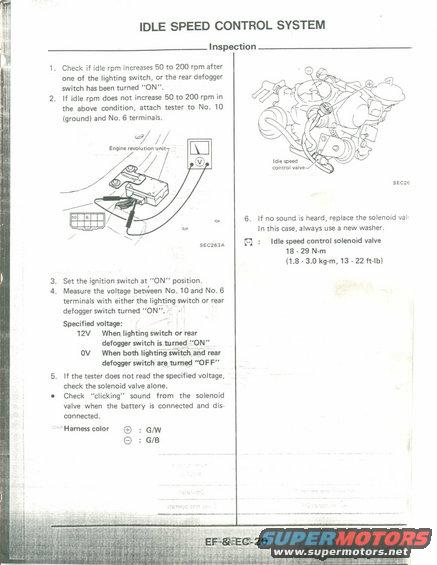
This diagram details the inspection process for an idle speed control system, including voltage checks and component specifications.
IDLE SPEED CONTROL SYSTEM Check if idle rpm increases 50 to 200 rpm after one of the lighting switch, or the rear defogger switch has been turned ON". If idle rpm does not increase 50 to 200 rpm in the above condition, attach tester to No. 10 (ground) and No.6 terminals, 6/ // Engine revolution unit seczsaA . Set the ignition switch at ON" position. Measure the voltage between No. 10 and Not 6 terminals with either the lighting switch or rear defogger switch turned ON. Vi ' Specified voltage: 12V When, lighting switch or rear defogger switch ismrned ON'V' ov When both lighting stitch and 'rear defogger switch are turned "OFF" If the tester does not read the specified voltage, check the solenoid valve alone. Check clicking" sound from the solenoid valve when the battery is connected and dis~ connectedi 'HarnesscoIor @ : G/W @ : G/B Inspection Idle speed control valve 55:25 6. If no sound is heard, replace the solenoid val In this case, always use a new washer. {C} : Idle speed control solenoid valve 18 - 29 N~m (1.8 - 3.0 kg.m, 13 - 22 ft-Ib)
Comments
More from this build


No comments yet.