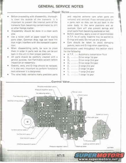
This diagram illustrates the components and functions of a control valve assembly.
GENERAL SERVICE NOTES Repair Notes Before proceeding with disassembly, thoroughr ly clean the outside of the transaxie. It is important to prevent the internal parts of the transaxle from becoming contaminated by dirt or other foreign matter. Disassembly should be done in a clean work area Use a nylon cloth or paper towel for wiping parts clean. Common shop rags can leave lint that might interfere with the transaxle's opera- tion. When disassembling parts, be sure to place them in order in parts rack so they can be put back in the unit in their proper positions. Ail parts should be carefully cleaned with a general purpose, non-flammable solvent before inspection or reassembly. Gaskets, seals, and O-rings should be replaced It is also very important to perform functional tests whenever it is designated The valve body contains many precision parts Throttle modulator valve Pressure modier valve In mducing valve lst-an control valve lst~2nd shun valve 2nd-3rd shift valve_/ 3rd~2nd downsmlt valve and requires extreme care when pans are removed and serviced, Place removed parts on a parts rack so they can be put back in the valve body in the same positions and se quences, Care will also prevent springs and small parts from becoming scattered or lost, 0 Before assembly, apply a coat of recommended A.T.F. to all parts. Vaseline may be applied to OArings and seals, Do not use any grease. 0 Care should be taken to avoid damaging gaskets, seals and O<rings when assembling. Abbreviations used throughout this section stand for the following: Automatic transmission fluid Drive range is! gear Drive range 2nd gear Drive range 3rd gear 2 range 2nd gear 2 range 151 gear 1 range 2nd gear 1 range lst gear 0.0.0000 Control Valve YManual valve , Yperm valve Snead cut valve Pulsar: valve snroaa
Comments
More from this build


No comments yet.