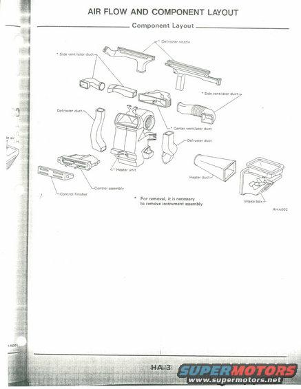
This diagram illustrates the air flow and component layout for a vehicle's heating and ventilation system.
AIR FLOW AND COMPONENT LAYOUT '91 T1 1.4 Component Layout Duroster nozzle ' 52d: venvlamr dun .r ' S|de vennlaxor dun Defrnsur duct Canter ventilator dun Defroster dun Heater duct Control asumhlv I Control nisher ' For rnmovul, it in nonnary to remove instrument assembly an A002
Comments
More from this build


No comments yet.