Hyundai Accent G4ED M/T MFI Wiring Diagram SD313-3 - Ignition Coils, ECM Pins
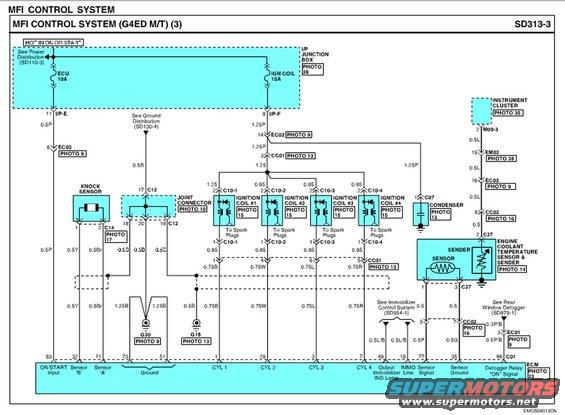
MFI control system wiring diagram (sheet 3) with color-coded ignition coil, knock sensor and coolant temperature sensor circuits.
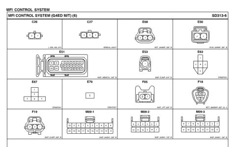
This document is page 3 of the MFI (Multiport Fuel Injection) Control System wiring diagram, sheet SD313-3, for the G4ED engine with manual transmission (M/T). Power comes from the I/P Junction Box via a 10A ECU fuse and a 15A IGN COIL fuse, hot in ON or START (see Power Distribution SD110-3). The diagram shows the knock sensor (connector C14) wired through joint connector C12 to ECM pins 32 (Sensor 'B') and 11 (Sensor 'A'), and four ignition coils (#1–#4 via connectors C10-1 through C10-4) driven by ECM pins 1, 29, 3, and 7 with 0.75B, 0.75W, 0.75L and 0.75R wires respectively. A condenser (C07) and the engine coolant temperature sensor & sender (C27) are shown, with the sender feeding the instrument cluster and the sensor feeding ECM pins 77 (Sensor Signal) and 35 (Sensor Ground). Additional ECM circuits include pin 83 ON/START input, pins 73/51 ground (to G20 and G18), pin 48 immobilizer indicator lamp output, pin 18 IMMO line (to Immobilizer Control System SD954-1), and pin 66 defogger relay "ON" signal (to Rear Window Defogger SD879-1). Wire gauges/colors and photo references for each connector are included.
Is this accurate? Sign in to help verify it.
Frequently asked questions
- What fuses power the MFI control system on the G4ED M/T?
- Per the diagram, a 10A ECU fuse and a 15A IGN COIL fuse in the I/P Junction Box, hot in ON or START (see Power Distribution SD110-3).
- Which ECM pins drive the four ignition coils?
- CYL 1 = pin 1 (0.75B wire), CYL 2 = pin 29 (0.75W), CYL 3 = pin 3 (0.75L), CYL 4 = pin 7 (0.75R), via connectors C10-1 through C10-4.
- Which ECM pins connect to the knock sensor?
- The knock sensor (connector C14, through joint connector C12) connects to ECM pin 32 (Sensor 'B', 0.5Y wire) and pin 11 (Sensor 'A', 0.5Br wire).
- Where does the engine coolant temperature sensor signal go?
- The ECT sensor & sender use connector C27. The sensor signal goes to ECM pin 77 (Sensor Signal, 0.5P) with sensor ground at pin 35 (0.5G); the sender side feeds the instrument cluster via M09-3.
- What are the ground points shown in this diagram?
- G20 [PHOTO 9] via 1.25B wires from ECM pins 73 and 51, and G18 [PHOTO 13] via a 0.5B wire.
Comments
More from this build




No comments yet.