Home/
Registry/
Hyundai/
Accent/
2006-2011/
2008 Hyundai Accent/
Photo
supermotors.net/registry/media/1155057
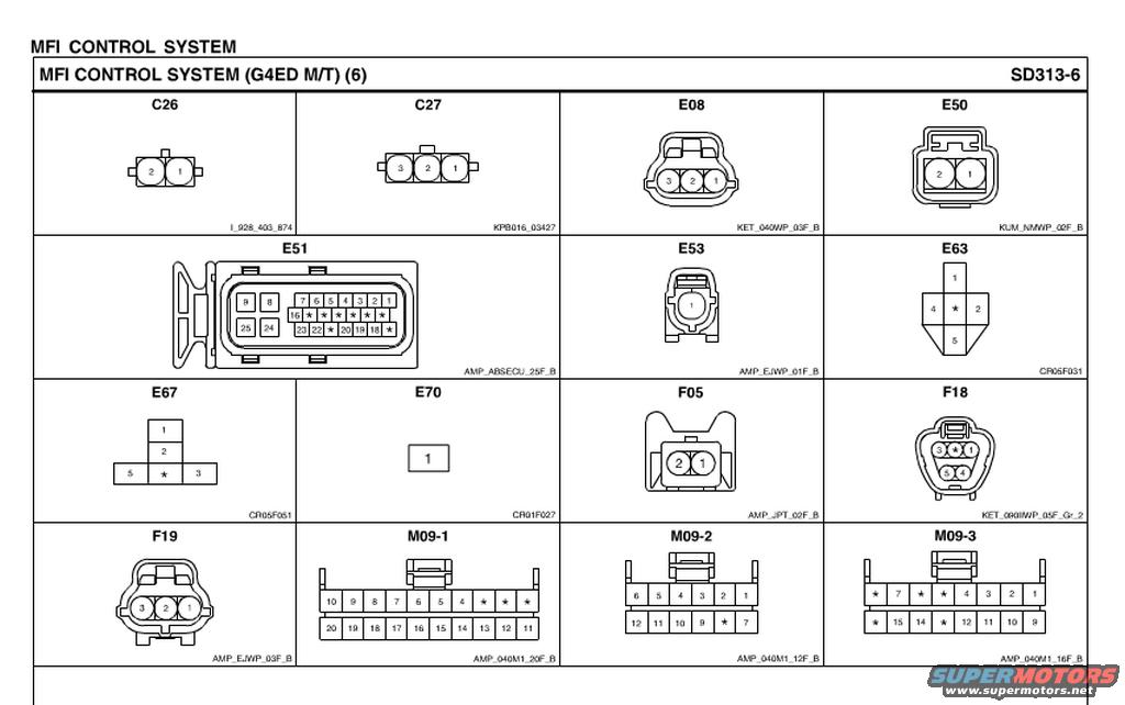
Hyundai Accent G4ED MFI Control System Connector Pinouts (SD313-6)
Reference · 2006-2011 AccentAll 12 wiring diagrams
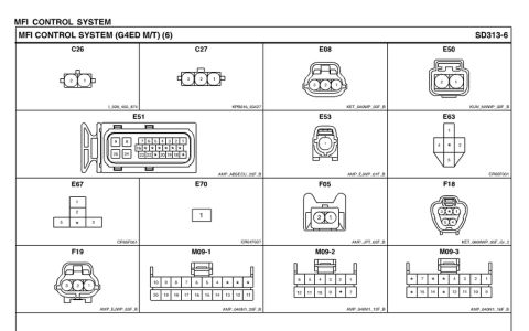


Connector identification chart (sheet 6) showing terminal face views and part numbers for connectors C26 through M09.
Part of 2006-2011 Hyundai Accent Wiring Diagrams
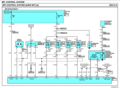
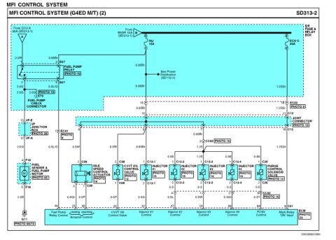
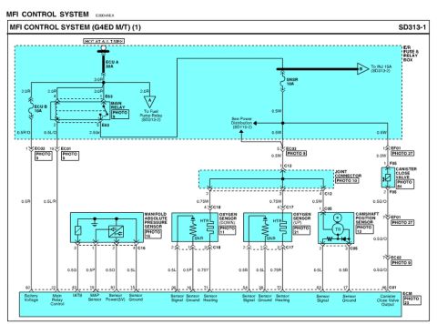
This document is page SD313-6 of a wiring diagram set covering the MFI (Multiport Fuel Injection) Control System for a vehicle with the G4ED engine and manual transmission (M/T). Rather than showing circuit wiring, this page is a connector reference sheet showing the physical face views and pin numbering of fifteen harness connectors used in the MFI control circuit: C26, C27, E08, E50, E51, E53, E63, E67, E70, F05, F18, F19, M09-1, M09-2, and M09-3. Each connector illustration shows the cavity/pin arrangement (with asterisks marking unused positions) and is captioned with a connector housing manufacturer code such as AMP_ABSECU_25F_B, KET_040WP_03F_B, KUM_NMWP_02F_B, or CR05F031. Connectors range from single-pin (E53, E70) to a 25-position ECU-style connector (E51) and multi-row 12/16/20-pin M09 connectors. A reader can use this sheet to identify connector shapes, locate specific pin numbers when probing or back-probing circuits during MFI system diagnosis, and cross-reference connector part codes. It complements the companion MFI wiring diagram pages 1-5 in the same set.
Is this accurate? Sign in to help verify it.
Frequently asked questions
- What engine and transmission does this MFI wiring diagram page apply to?
- The header states it covers the MFI Control System for the G4ED engine with manual transmission (M/T), page SD313-6.
- Which connectors are shown on this connector view page?
- C26, C27, E08, E50, E51, E53, E63, E67, E70, F05, F18, F19, M09-1, M09-2, and M09-3.
- How many pins does connector E51 have?
- E51 is a 25-position connector (code AMP_ABSECU_25F_B) with pins numbered up to 25; several positions are marked with asterisks as unused.
- What is the connector code for M09-1?
- M09-1 is a 20-position connector with code AMP_040M1_20F_B; the second row carries pins 11-20.
- What do the asterisks in the connector drawings mean?
- Asterisks mark cavity positions that are not assigned a pin number (unused/unpopulated positions) in the connector views.
No comments yet.