Hyundai Accent G4ED MFI Wiring Diagram SD313-2 - Fuel Pump, Injectors, ECM Pins
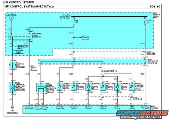
MFI control system wiring diagram (sheet 2) with color-coded fuel pump relay, injector and purge valve circuits and connectors.
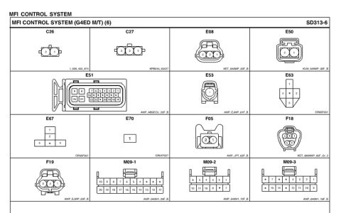
This is page 2 of the MFI (Multiport Fuel Injection) control system wiring diagram for a Hyundai with the G4ED engine and manual transmission, drawing number SD313-2. The diagram shows power flowing from the E/R (engine room) fuse and relay box through the ECU A 30A feed, SNSR 10A fuse, INJ 15A fuse, and ECU C 20A fuse. It details the fuel pump relay circuit (connector E67), the fuel pump check connector (E70), and the fuel sender/fuel pump motor (connector F18) grounding at G11. Through a joint connector, 0.85Br wiring distributes power to the idle speed control actuator (C09), CVVT oil control valve (C08), fuel injectors #1-#4 (C13-1 through C13-4), and the purge control solenoid valve (C26). Each component's control side returns to the ECM with labeled pin numbers: pin 49 (fuel pump relay control), pins 25/90 (ISC actuator closing/opening), 92 (CVVT valve), 91/47/24/68 (injectors #1-#4), 69 (PCSV control), and pin 6 of C01 (main relay 'ON' input). Wire colors and gauges (e.g., 0.85Br, 1.25Gr, 0.5G, 0.5L, 0.5W, 0.5Gr, 0.5Y, 2.0G, 2.0R, 2.0B) are noted throughout, with photo references for connector locations.
Is this accurate? Sign in to help verify it.
Frequently asked questions
- Which ECM pins control the fuel injectors on the G4ED MFI system?
- Per the diagram, ECM pin 91 controls Injector #1, pin 47 controls Injector #2, pin 24 controls Injector #3, and pin 68 controls Injector #4.
- What fuse feeds the injectors in this MFI control system?
- The INJ 15A fuse in the E/R fuse & relay box feeds the injector power circuit via 0.85Br wiring.
- What ECM pin controls the fuel pump relay?
- ECM pin 49 (Fuel Pump Relay Control), via a 0.5L/O wire to the fuel pump relay at connector E67.
- What connector is used for the fuel sender and fuel pump motor?
- Connector F18 (pins 4 and 5), with a 2.0B wire grounding at G11 (PHOTO 66/70).
- Which ECM pins operate the idle speed control actuator?
- Pins 25 (closing) and 90 (opening) control the idle speed control actuator through connector C09, using 0.5Gr and 0.5P wires.
Comments
More from this build


No comments yet.