Hyundai Accent Starting System Wiring Diagram SD360-1 - Starter Relay & Circuit

Starting system wiring diagram (sheet 1) with color-coded battery, starter relay, ignition switch and starter motor circuits.
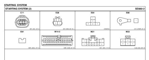
This document is one page of a factory-style wiring diagram, sheet SD360-1 'Starting System (1)', showing the starter circuit for a Hyundai Accent (uploaded as a 2008 Accent document). Power flows from the battery through 15B cables to the starter and through the E/R fuse & relay box, where the IGN #2 40A fuse and the START RELAY (connector E64) are located. The ignition switch (HOT AT ALL TIMES, positions LOCK/ACC/ON/START, PHOTO 36) feeds a START 10A fuse in the I/P junction box via connector M22 on a 2.0W wire. The diagram branches for vehicles with and without an immobilizer (0.5P vs 0.5W wires), routing through the ICM relay box burglar alarm relay (M21, terminals 30/85/86/87a) and to the BCM via connector M14-2 (0.5Br/B). Manual-transmission cars use an ignition lock switch (E28) grounded at G13; automatic cars use the transaxle range switch (C11, showing R/N/D positions) grounded at G20 via joint connector C12. The starter motor detail shows the start solenoid, magnetic lever, pinion gear, overrunning clutch, and flywheel. Wire gauges/colors (2.0G, 2.0R/B, 0.3B/O, 0.5B, etc.), connector pin numbers, and photo references for component locations are included, along with ground distribution cross-references SD130-3 and SD130-4.
Is this accurate? Sign in to help verify it.
Frequently asked questions
- What fuse protects the Hyundai Accent starting circuit?
- Two fuses are shown: the IGN #2 40A fuse in the engine room (E/R) fuse & relay box, and a START 10A fuse in the I/P junction box (PHOTO 28/29).
- Where is the start relay located?
- The start relay is in the E/R fuse & relay box, at connector E64 (pins 1, 2, 3, 5), referenced to PHOTO 9.
- How does the starting circuit differ between manual and automatic transmissions?
- Manual (M/T) models route through an ignition lock switch at connector E28 with ground at G13; automatic (A/T) models route through the transaxle range switch at connector C11 (positions R, N, D shown), grounding at G20 through joint connector C12.
- What wire colors are used in the starter circuit?
- The diagram shows 2.0W from the ignition switch, 2.0G from the IGN #2 fuse, 2.0R/B to the start solenoid, 0.3B/O and 0.3B for the M/T lock switch, 0.5B/0.3G/0.5W/0.5P for A/T and immobilizer branches, 0.5Br/B to the BCM, and 15B battery cables.
- Does the immobilizer affect the starting circuit wiring?
- Yes. The diagram splits at I/P-F/I/P-N: 'With IMMO' uses a 0.5P wire and 'W/O IMMO' uses a 0.5W wire, and there are further branches for with/without burglar alarm through the ICM relay box burglar alarm relay and the BCM.
Comments
More from this build

No comments yet.