Hyundai Accent G4ED M/T MFI Control System Wiring Diagram SD313-4 (Page 4)
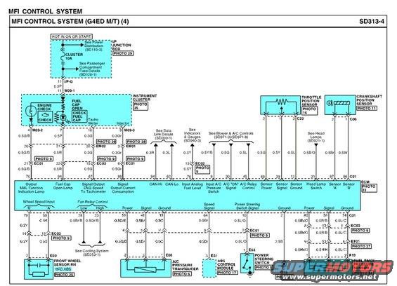
MFI control system wiring diagram (sheet 4) with color-coded circuits for cluster, throttle and crankshaft position sensors.
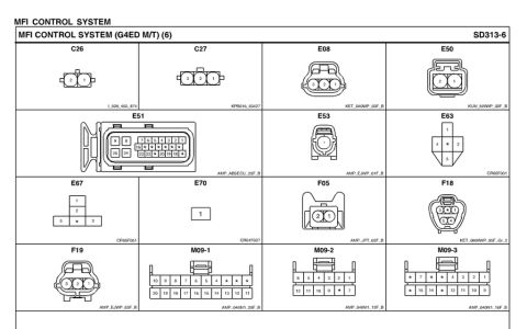
This document is page 4 of the Multiport Fuel Injection (MFI) control system wiring diagram for a Hyundai Accent with the G4ED engine and manual transmission (diagram SD313-4). It shows the circuit from the CLUSTER 10A fuse (hot in ON or START, fed from the I/P junction box) to the instrument cluster warning lamps (Engine Check / MIL, Fuel Cap Open), tachometer signal, and CAN-Hi/CAN-Lo lines. The diagram details ECM connector C01 pin assignments, including pin 70 (MIL output), 94 (fuel cap open lamp), 67 (engine speed signal to tachometer), 62/64 (CAN-Hi/CAN-Lo), 8 (A/C pressure switch input), 30 (A/C ON signal), 45 (A/C relay control), plus sensor power/signal/ground pins for the throttle position sensor (C23), crankshaft position sensor (C06), A/C pressure transducer (E08), fuel tank pressure sensor (F19), front wheel speed sensor RH (E50, w/o ABS), ABS control module (E31), power steering switch (E53), and fan relay control (low/high). Wire colors and gauges (e.g., 0.5G/B, 0.3Gr, 0.5Br/O, 2.5B) and intermediate connectors (M09, EM01/EM02, EC01/EC02/EC03, EF01) are labeled, along with cross-references to other diagrams (SD110-3, SD120-1, SD200-1, SD253-1, SD921-1, SD940-3, SD971-3/8).
Is this accurate? Sign in to help verify it.
Frequently asked questions
- What fuse powers the instrument cluster circuit in this MFI diagram?
- The CLUSTER 10A fuse, which is hot in ON or START and fed via the I/P junction box (see Power Distribution SD110-3 and fuse details SD120-1).
- Which ECM pins carry the CAN bus signals?
- ECM connector C01 pin 62 is CAN-Hi and pin 64 is CAN-Lo.
- Which ECM pin drives the malfunction indicator (check engine) lamp?
- Pin 70 of connector C01, labeled 'Output MAL Function Indication Lamp'; pin 94 drives the Fuel Cap Open lamp.
- What connectors are used for the throttle position and crankshaft position sensors?
- The throttle position sensor uses connector C23 (pins 2, 1, 3) and the crankshaft position sensor uses connector C06 (pins 2, 1).
- Which ECM pins control the cooling fan relays?
- Fan relay control uses ECM pins 28 (Low) and 23 (High), with reference to the cooling system diagram SD253-1.
Comments
More from this build



No comments yet.