Home/
Registry/
Ford/
F-100/
1980-1983/
1982 Ford F-100/
Photo
supermotors.net/registry/media/1041610
Ford F-250 4x4 Transfer Case Removal & Installation Procedure (06-07-02)
Reference · 1980-1983 F-100All 1 service procedures

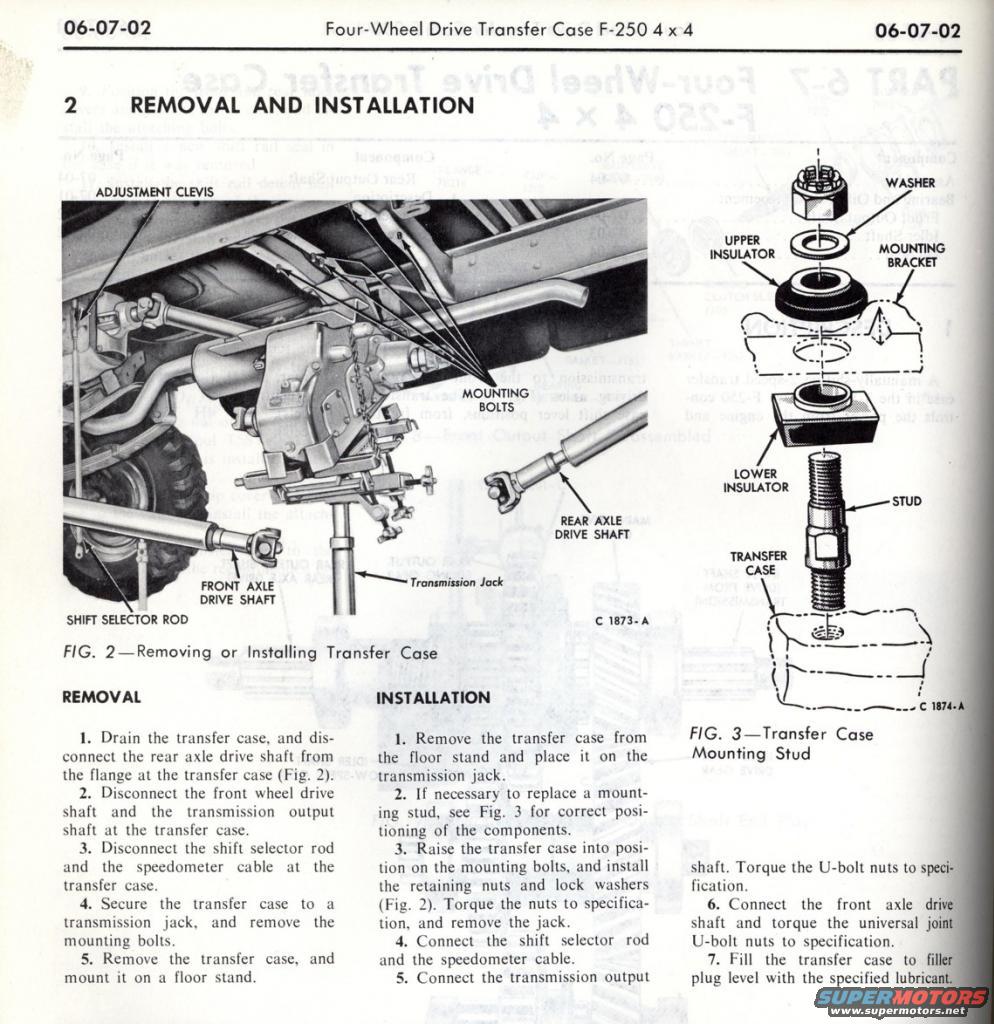
Ford shop-manual page (06-07-02) covering F-250 4x4 transfer case removal and installation, including mounting-stud insulators and U-bolt/universal-joint torque-to-spec steps.
Part of 1980-1983 Ford F-100 Service Procedures
This is a scanned page (section 06-07-02) from a Ford factory shop manual covering the four-wheel drive transfer case on the F-250 4x4. Section 2, 'Removal and Installation,' provides step-by-step procedures. The removal procedure (5 steps) covers draining the transfer case, disconnecting the rear axle drive shaft at the transfer case flange, disconnecting the front wheel drive shaft and transmission output shaft, disconnecting the shift selector rod and speedometer cable, supporting the unit on a transmission jack, removing the mounting bolts, and placing the case on a floor stand. The installation procedure (7 steps) reverses the process, including replacing mounting studs if needed (per Fig. 3), torquing retaining nuts and U-bolt nuts to specification, reconnecting the shift selector rod and speedometer cable, and filling the transfer case to the filler plug level with the specified lubricant. Fig. 2 (illustration C 1873-A) shows the transfer case being removed or installed on a transmission jack, with callouts for the adjustment clevis, mounting bolts, front and rear axle drive shafts, and shift selector rod. Fig. 3 (C 1874-A) is an exploded view of the transfer case mounting stud assembly: washer, upper insulator, mounting bracket, lower insulator, stud, and transfer case. No specific torque values or part numbers are printed on this page.
Is this accurate? Sign in to help verify it.
Frequently asked questions
- How do you remove the transfer case on a Ford F-250 4x4?
- Drain the transfer case, disconnect the rear axle drive shaft at the transfer case flange, disconnect the front wheel drive shaft and transmission output shaft, disconnect the shift selector rod and speedometer cable, secure the case to a transmission jack, remove the mounting bolts, then remove the transfer case and mount it on a floor stand.
- What components make up the transfer case mounting stud assembly?
- Per Fig. 3, the assembly includes a washer, upper insulator, mounting bracket, lower insulator, stud, and the transfer case itself.
- What must be disconnected at the transfer case before removal?
- The rear axle drive shaft, the front wheel drive shaft, the transmission output shaft, the shift selector rod, and the speedometer cable.
- How is the transfer case refilled after installation?
- Step 7 of installation says to fill the transfer case to filler plug level with the specified lubricant.
- What fasteners must be torqued to specification during installation?
- The transfer case retaining nuts (with lock washers), the transmission output shaft U-bolt nuts, and the front axle drive shaft universal joint U-bolt nuts.


No comments yet.