Home/
Registry/
Ford/
F-100/
1980-1983/
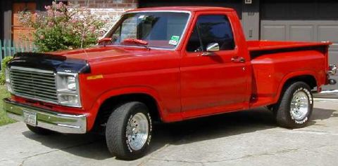
1982 Ford F-100/
Photo
supermotors.net/registry/media/1041611
Ford NP205 Transfer Case Installation Diagram F-250 - Linkage Adjustment & Torque

Ford F-250 New Process 205 transfer case installation drawing showing linkage, mounting bracket and torque specs in chassis.
This is a scanned page (section 16-84-4) from a Ford factory shop manual covering the New Process 205 transfer case. The page presents Figure 3, an exploded/installation illustration of the Model 205 transfer case as installed in an F-250. The main view shows the transfer case mounted behind the transmission with its shift linkage, mounting bracket, support bar, insulator, and hardware. Labeled components include the shift lever (7A400), adjustment rod (7B051), bracket (7F035), bar (7F034), insulator (4A037), washer (18041), and nut (34663). Torque specifications are called out on the drawing: 15-25 ft-lb for several fasteners and 70-90 ft-lb for one attachment. Directional arrows T, U, V, W, X, Y, and Z indicate detail views that are shown on Figure C2711-A. An adjustment procedure for the Model 435 manual transmission states the transfer case must be in 4-wheel low (cross link assembly all the way in), dimension "A" from the rear face of the transmission must be 3.94/3.82, and rod 7B051 must be adjusted to correct length with the lock nut tightened at the clevis. Automatic transmission linkage adjustment is referenced to Figure C2711-A. The figure ID is C2710-A.
Is this accurate? Sign in to help verify it.
Frequently asked questions
- What torque specs are shown for the NP205 transfer case installation?
- The diagram calls out 15-25 ft-lb at several fastener locations and 70-90 ft-lb at one mounting point.
- How is the transfer case shift linkage adjusted with the Model 435 manual transmission?
- The transfer case must be in 4-wheel low (cross link assembly all the way in), dimension "A" from the rear face of the transmission must be 3.94/3.82, then rod 7B051 is adjusted to the correct length and the lock nut tightened at the clevis.
- What part numbers are labeled in the NP205 installation diagram?
- Lever 7A400, rod 7B051, bar 7F034, bracket 7F035, insulator 4A037, washer 18041, and nut 34663.
- Where are the detail views T through Z shown?
- The page states that details of views T–U–V–W–X–Y–Z are shown on Figure C2711-A.
- Which truck is this transfer case installation figure for?
- The figure caption states 'Model 205 Transfer Case Installation—F-250'.
Comments
More from this build






No comments yet.