Home/
Registry/
Ford/
F-100/
1980-1983/
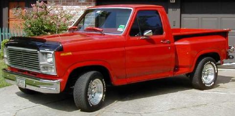
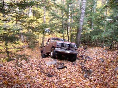
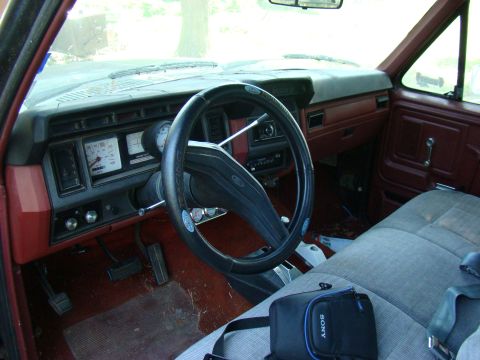
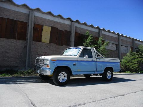
1982 Ford F-100/
Photo
supermotors.net/registry/media/1041612
Ford F-250 NP205 Transfer Case Installation Diagram - Linkage & Torque Specs
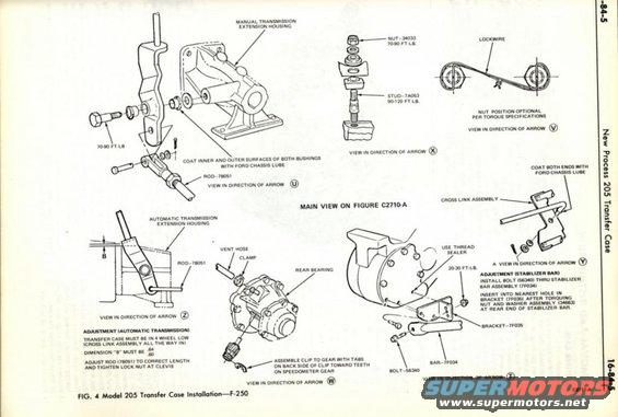
Ford F-250 New Process 205 transfer case installation exploded detail views showing linkage, bushings, bearing and stabilizer bar assembly.
This is a scanned page (16-84-5) from a Ford factory service manual covering the New Process 205 transfer case. It presents Figure 4, "Model 205 Transfer Case Installation—F-250," showing multiple exploded/detail views (labeled by arrow directions T, U, V, W, X, Y, Z) that supplement a main view on Figure C2710-A. The page details shift linkage installation for both manual and automatic transmission extension housings, calling out rod 7B051 and the instruction to coat inner and outer bushing surfaces with Ford chassis lube. Torque specifications include 70-90 ft-lb for the rod attaching bolt and nut 34033, and 90-120 ft-lb for stud 7A053; nut position is optional per torque specifications with lockwire shown. The speedometer gear view shows vent hose, clamp, rear bearing, and instructions to assemble the clip with tabs toward the gear teeth. Adjustment procedures are given for the automatic transmission linkage (transfer case in 4-wheel low, dimension "B" must be .64/.60, adjust rod 7B051 and tighten lock nut at clevis) and for the stabilizer bar (bolt 56340 through stabilizer bar assembly 7F034 into bracket 7F035, torque 20-30 ft-lb with thread sealer, nut and washer assembly 34663). Illustration reference number C2711-A appears at bottom right.
Is this accurate? Sign in to help verify it.
Frequently asked questions
- What torque is specified for the transfer case stud 7A053?
- Stud 7A053 is torqued to 90-120 ft-lb, and nut 34033 is torqued to 70-90 ft-lb.
- How is the automatic transmission transfer case linkage adjusted?
- The transfer case must be in 4-wheel low (cross link assembly all the way in), dimension "B" must be .64/.60, then adjust rod 7B051 to correct length and tighten the lock nut at the clevis.
- How is the stabilizer bar adjusted on the NP205?
- Install bolt 56340 through stabilizer bar assembly 7F034, insert into the nearest hole in bracket 7F035 after torquing the nut and washer assembly (34663) at the rear end of the stabilizer bar. The bracket fasteners are torqued 20-30 ft-lb with thread sealer.
- What lubricant is specified for the linkage bushings?
- Coat the inner and outer surfaces of both bushings, and both ends of the cross link, with Ford chassis lube.
- How should the speedometer gear clip be installed?
- Assemble the clip to the gear with the tabs on the back side of the clip toward the teeth on the speedometer gear.
Comments
More from this build
No comments yet.