Home/
Registry/
Ford/
Bronco/
1987-1991/
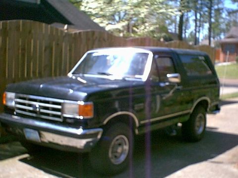
“Eddie Bauer”/
Photo
supermotors.net/registry/media/1046699
Ford Motorsport F-Series Mass Air Install Instructions Page 5 - Intake Removal

Page 5 of the Ford Motorsport Mass Air install: remove upper intake manifold (T40 Torx in 1/4-in socket on 6-in extension), disconnect the 8 production fuel injector connectors and the 60-pin EEC-IV engine harness.
This is page 5 of 9 of the Ford Motorsport (Ford Racing / FMS) F-Series Mass Air conversion installation instructions, document number IS-M-9000-T51*, dated 1/21/93. It covers Steps 12 through 19 of the mass air meter installation procedure. The steps described include disconnecting the PCV hose from the PCV valve at the rear of the passenger side valve cover, removing the shield over the front two upper intake manifold bolts, removing the upper intake manifold hex head bolts, and loosening the middle intake bolt on the throttle body using a T40 TORX bit taped into a 1/4" socket with a 6" extension (illustrated in Figure 7 with Detail "A"). A note advises taping over the intake openings in the lower intake manifold. The page then instructs disconnecting the eight fuel injector connectors on the production harness (Figure 8, Lower Intake/Injector Harness), positioning the production fuel injector harness away from heat sources or sharp edges, locating the EEC-IV processor/60-pin connector on the driver's side firewall, and disconnecting the 60-pin engine harness connector from the EEC-IV processor (referencing Figure 9 on a subsequent page). Two exploded-view illustrations show upper/lower intake manifold and gasket removal and the injector harness location.
Is this accurate? Sign in to help verify it.
Frequently asked questions
- How do you loosen the middle intake bolt on the throttle body during the F-Series Mass Air install?
- Per Step 15, tape a T40 TORX bit into a 1/4" socket, then tape the Torx bit/socket to a 6" long 1/4" drive extension to loosen the middle intake bolt, then remove the upper intake manifold (see Figure 7).
- How many fuel injector connectors must be disconnected?
- Step 16 says to disconnect the (8) fuel injector connectors on the production harness, as shown in Figure 8.
- Where is the EEC-IV processor/60-pin connector located?
- Step 18 states the EEC-IV processor/60 pin connector is on the driver's side firewall; Step 19 instructs disconnecting the 60 pin engine harness connector from the EEC-IV processor.
- What should be done after removing the upper intake manifold?
- The document notes: place tape over the intake openings in the lower intake manifold to keep debris out.
- Where is the PCV valve that must be disconnected?
- Step 12 says to disconnect the PCV hose from the PCV valve located at the rear of the passenger side valve cover.
Comments
More from this build


No comments yet.