Home/
Registry/
Ford/
Bronco/
1987-1991/
“Eddie Bauer”/
Photo
supermotors.net/registry/media/1046700
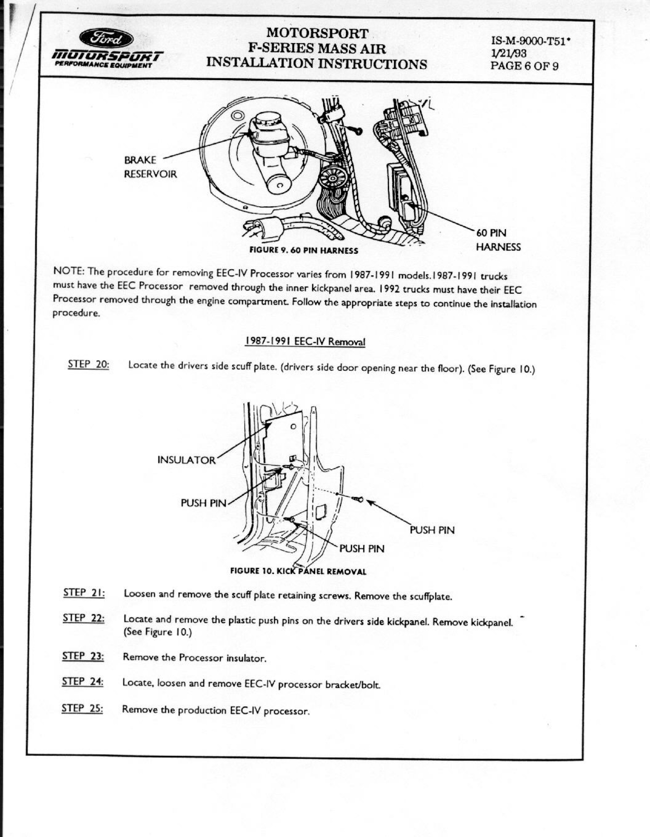
Ford Motorsport F-Series Mass Air Install Page 6 - EEC-IV Removal 1987-1992
Reference · 1987-1991 BroncoAll 95 service procedures
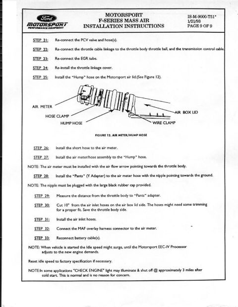
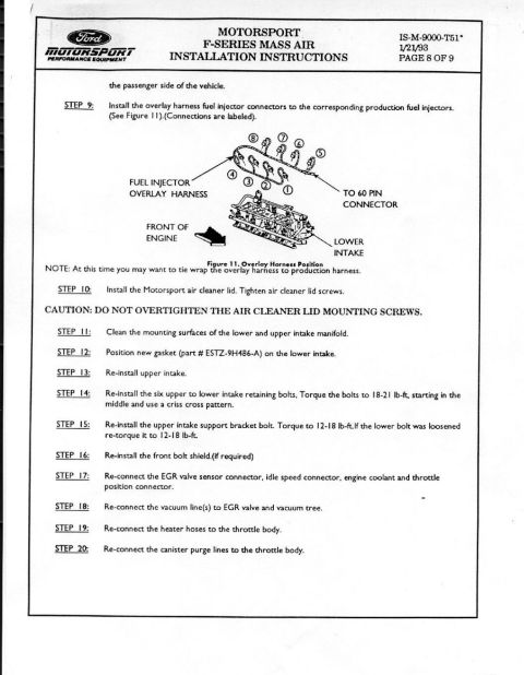
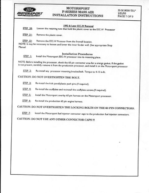
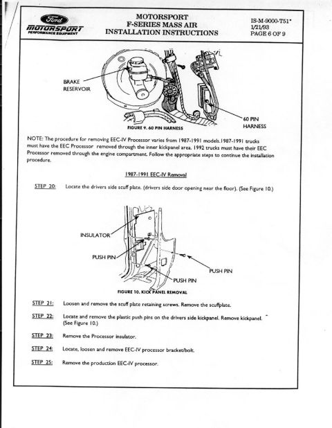
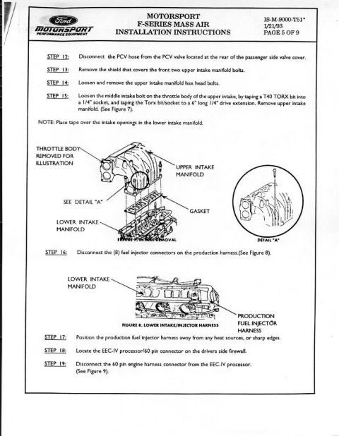
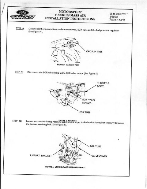
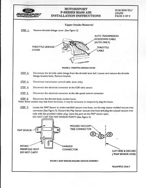











Page 6 of the Ford Motorsport Mass Air install: 60-pin harness and 1987-1991 EEC-IV processor removal through the driver's-side kick panel (scuff plate, push pins, processor insulator and bracket).
Part of 1987-1991 Ford Bronco Service Procedures
This is page 6 of 9 from Ford Motorsport Performance Equipment's installation instructions (document IS-M-9000-T51*, dated 1/21/93) for the F-Series Mass Air conversion kit. The page covers removal of the factory EEC-IV processor (engine computer). Figure 9 illustrates the 60-pin harness location in the engine compartment near the brake reservoir. A note explains that the removal procedure differs by year: 1987-1991 trucks require removing the EEC processor through the inner kick panel area, while 1992 trucks require removal through the engine compartment. The page then details the 1987-1991 EEC-IV removal procedure in Steps 20-25: locating the driver's side scuff plate near the floor of the door opening, removing the scuff plate retaining screws, removing plastic push pins to take off the driver's side kick panel (shown in Figure 10 with insulator and push pin locations), removing the processor insulator, removing the EEC-IV processor bracket/bolt, and finally removing the production EEC-IV processor. This page is part of a multi-page mass air flow (MAF) conversion procedure applicable to Ford F-Series trucks and related vehicles like the Bronco.
Is this accurate? Sign in to help verify it.
Frequently asked questions
- Where is the EEC-IV processor removed from on 1987-1991 Ford trucks?
- On 1987-1991 trucks the EEC processor must be removed through the inner kick panel area on the driver's side, after removing the scuff plate and kick panel.
- How is EEC-IV removal different on 1992 trucks?
- The document notes that 1992 trucks must have their EEC processor removed through the engine compartment, unlike 1987-1991 models which use the inner kick panel area.
- What steps are involved in removing the EEC-IV processor on 1987-1991 models?
- Steps 20-25: locate the driver's side scuff plate near the floor of the door opening, loosen and remove the scuff plate retaining screws, remove the plastic push pins and the kick panel, remove the processor insulator, remove the EEC-IV processor bracket/bolt, then remove the production EEC-IV processor.
- What does Figure 9 show?
- Figure 9 shows the 60 pin harness location, with callouts for the brake reservoir and the 60 pin harness.
- What document number and date does this instruction page carry?
- It is Ford Motorsport document IS-M-9000-T51*, dated 1/21/93, page 6 of 9.






No comments yet.