Home/
Registry/
Ford/
Bronco/
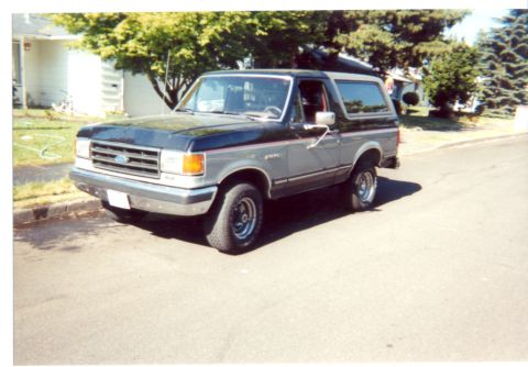
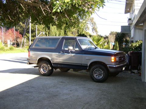
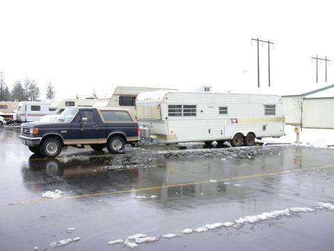
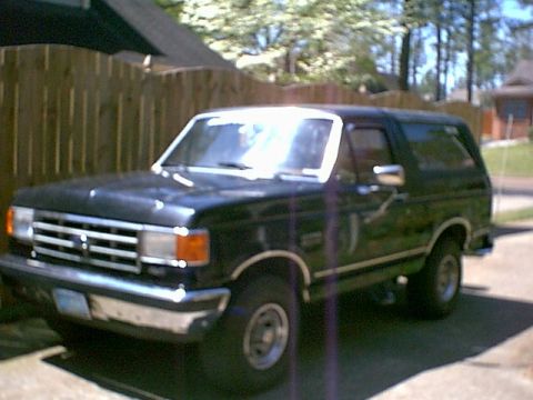
1987-1991/
“Eddie Bauer”/
Photo
supermotors.net/registry/media/1046703
Ford Motorsport F-Series Mass Air MAF Install Instructions Page 9 - Final Steps
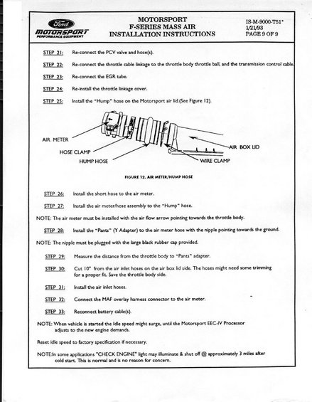
Page 9 (final) of the Ford Motorsport Mass Air install: reconnect PCV/EGR/throttle, install hump hose and air meter (flow arrow toward throttle body), and the Pants Y-adapter with nipple capped; cut 1 inch from inlet hoses.
This is page 9 of 9 of the Ford Motorsport F-Series Mass Air (MAF) conversion installation instructions, document IS-M-9000-T51*, dated 1/21/93. It covers the final steps (Steps 21–33) of the installation: reconnecting the PCV valve and hoses, throttle cable linkage and transmission control cable, EGR tube, and throttle linkage cover; installing the "Hump" hose on the Motorsport air box lid; installing the short hose and air meter/hose assembly (with a note that the air meter's airflow arrow must point toward the throttle body); installing the "Pants" Y-adapter with its nipple pointing down and plugged with the supplied rubber cap; measuring the throttle-body-to-adapter distance; cutting 10" from the air inlet hoses on the air box lid side; installing the air inlet hoses; connecting the MAF overlay harness connector to the air meter; and reconnecting the battery cables. Figure 12 illustrates the air meter/hump hose assembly, labeling the air meter, hose clamp, hump hose, wire clamp, and air box lid. Closing notes explain that idle speed may surge until the Motorsport EEC-IV processor adapts, idle should be reset to factory spec if needed, and a temporary CHECK ENGINE light within about 3 miles of a cold start is normal.
Is this accurate? Sign in to help verify it.
Frequently asked questions
- Which direction should the air meter be installed in the Ford Motorsport Mass Air kit?
- The air meter must be installed with the air flow arrow pointing towards the throttle body.
- How should the "Pants" Y-adapter be oriented and sealed?
- Install the "Pants" (Y Adapter) to the air meter hose with the nipple pointing towards the ground, and plug the nipple with the large black rubber cap provided.
- How much should be cut from the air inlet hoses?
- Cut 10" from the air inlet hoses on the air box lid side; the hoses might need some trimming for a proper fit. Save the throttle body side.
- Is it normal for the CHECK ENGINE light to come on after installing the Mass Air kit?
- Yes. In some applications the "CHECK ENGINE" light may illuminate and shut off at approximately 3 miles after a cold start. This is normal and no reason for concern.
- Why might the idle speed surge after starting the vehicle post-installation?
- The idle speed might surge when the vehicle is started until the Motorsport EEC-IV Processor adjusts to the new engine demands. Reset idle speed to factory specification if necessary.
Comments
More from this build


No comments yet.