Home/
Registry/
Ford/
Bronco/
1987-1991/
“Eddie Bauer”/
Photo
supermotors.net/registry/media/1046702
Ford Motorsport F-Series Mass Air Conversion Instructions - Page 8 of 9 (M-9000-T51)

Reference · 1987-1991 BroncoAll 95 service procedures
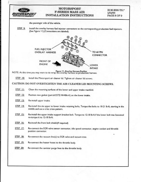
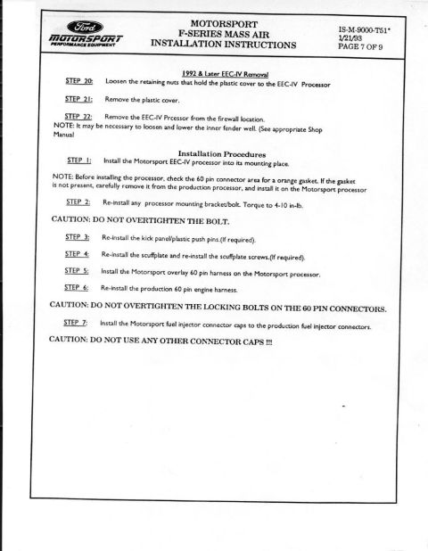
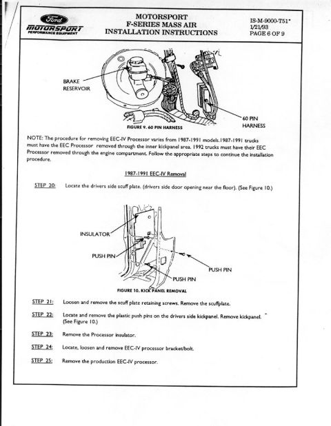
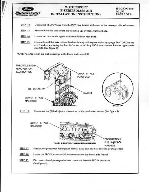
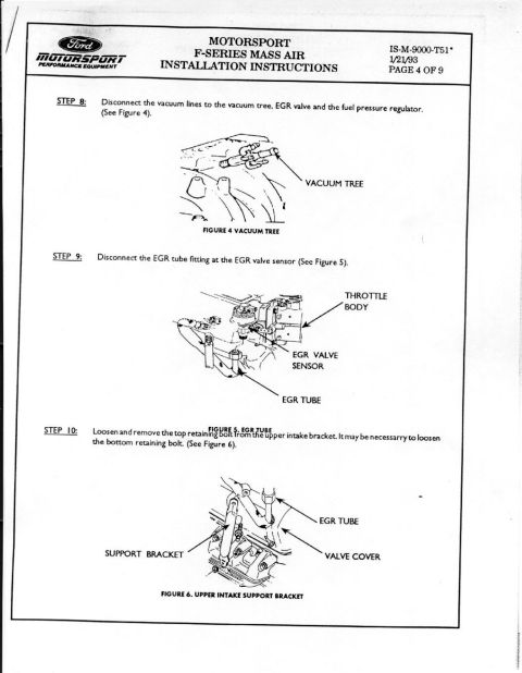










Page 8 of the Ford Motorsport Mass Air install: connect overlay fuel-injector harness, install air cleaner lid, reinstall upper intake with new gasket; bolts 18-21 lb-ft criss-cross, support bracket 12-18 lb-ft.
Part of 1987-1991 Ford Bronco Service Procedures
This is page 8 of 9 of the Ford Motorsport (FMS) F-Series Mass Air installation instructions, document IS-M-9000-T51*, dated 1/21/93. It covers steps 9 through 20 of the mass air conversion procedure. Step 9 instructs installation of the labeled overlay harness fuel injector connectors onto the eight production fuel injectors, illustrated in Figure 11, which shows the overlay harness position relative to the lower intake, the front of the engine, and the routing to the 60-pin connector. A note suggests tie-wrapping the overlay harness to the production harness. Subsequent steps cover installing the Motorsport air cleaner lid (with a caution not to overtighten the lid mounting screws), cleaning the intake mounting surfaces, positioning a new lower intake gasket (part # ESTZ-9H486-A), reinstalling the upper intake, torquing the six upper-to-lower intake bolts to 18-21 lb-ft in a criss-cross pattern starting from the middle, torquing the upper intake support bracket bolt to 12-18 lb-ft, reinstalling the front bolt shield if required, and reconnecting the EGR valve sensor connector, idle speed connector, engine coolant and throttle position connectors, vacuum lines to the EGR valve and vacuum tree, heater hoses, and canister purge lines to the throttle body.
Is this accurate? Sign in to help verify it.
Frequently asked questions
- What torque is specified for the upper to lower intake retaining bolts?
- The six upper-to-lower intake retaining bolts are torqued to 18-21 lb-ft, starting in the middle and using a criss-cross pattern (Step 14).
- What gasket part number is used on the lower intake during the FMS Mass Air installation?
- Step 12 specifies positioning a new gasket, part # ESTZ-9H486-A, on the lower intake.
- What torque is used for the upper intake support bracket bolt?
- Torque the upper intake support bracket bolt to 12-18 lb-ft; if the lower bolt was loosened, re-torque it to 12-18 lb-ft (Step 15).
- How are the overlay harness fuel injector connectors installed?
- Per Step 9, install the overlay harness fuel injector connectors to the corresponding production fuel injectors; the connections are labeled (see Figure 11), and the harness routes to a 60-pin connector. A note recommends tie-wrapping the overlay harness to the production harness.
- What connectors and lines get reconnected after reinstalling the upper intake?
- Reconnect the EGR valve sensor connector, idle speed connector, engine coolant and throttle position connectors (Step 17), the vacuum line(s) to the EGR valve and vacuum tree (Step 18), the heater hoses to the throttle body (Step 19), and the canister purge lines to the throttle body (Step 20).






No comments yet.