Home/
Registry/
Ford/
Bronco/
1987-1991/
“Eddie Bauer”/
Photo
supermotors.net/registry/media/1046704
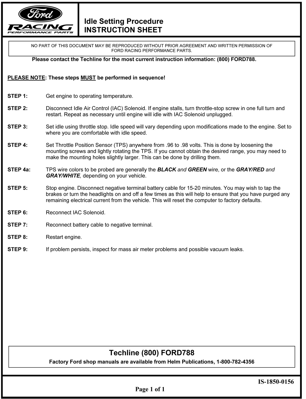
Ford Racing Idle Setting Procedure & TPS Adjustment Instruction Sheet IS-1850-0156
Reference · 1987-1991 BroncoAll 95 service procedures

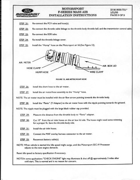
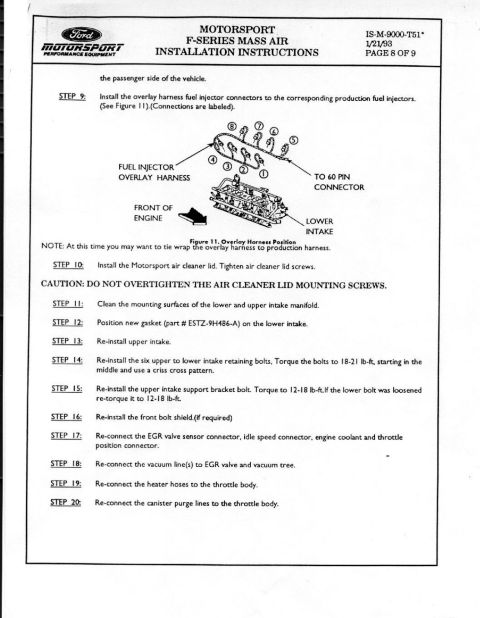
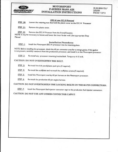
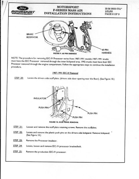










Ford Racing Performance Parts idle-setting instruction sheet (IS-1850-0156): disconnect IAC, set idle via throttle stop, set TPS to 0.96-0.98 volts on black/green or gray wires, reconnect IAC.
Part of 1987-1991 Ford Bronco Service Procedures
This is a one-page Ford Racing Performance Parts instruction sheet (document number IS-1850-0156) describing the official idle setting procedure for Ford EFI engines, typically performed after installing a mass air meter or other engine modifications. The sheet emphasizes that the nine steps must be performed in sequence: warm the engine to operating temperature; disconnect the Idle Air Control (IAC) solenoid and adjust the throttle-stop screw until the engine idles with the IAC unplugged; set idle speed via the throttle stop to a comfortable level; set the Throttle Position Sensor (TPS) to between .96 and .98 volts by loosening and rotating the sensor (drilling mounting holes larger if needed). It notes the TPS wires to probe are generally BLACK and GREEN, or GRAY/RED and GRAY/WHITE, depending on the vehicle. The procedure then calls for disconnecting the negative battery cable for 15-20 minutes (tapping the brakes or cycling headlights to purge residual current) to reset the computer to factory defaults, reconnecting the IAC solenoid and battery, and restarting the engine. If problems persist, the sheet advises checking for mass air meter problems and vacuum leaks. Techline contact (800) FORD788 and Helm Publications (1-800-782-4356) numbers are provided.
Is this accurate? Sign in to help verify it.
Frequently asked questions
- What voltage should the Throttle Position Sensor (TPS) be set to?
- The TPS should be set anywhere from .96 to .98 volts, done by loosening the mounting screws and lightly rotating the TPS. If the desired range can't be reached, the mounting holes may need to be drilled slightly larger.
- Which TPS wires should be probed when setting the voltage?
- Generally the BLACK and GREEN wires, or the GRAY/RED and GRAY/WHITE wires, depending on your vehicle.
- How do you reset the Ford computer to factory defaults in this procedure?
- Stop the engine and disconnect the negative battery cable for 15-20 minutes. Tapping the brakes or turning the headlights on and off a few times helps purge remaining electrical current, resetting the computer to factory defaults.
- What should you do if the engine stalls when the IAC solenoid is unplugged?
- Turn the throttle-stop screw in one full turn and restart. Repeat as necessary until the engine will idle with the IAC solenoid unplugged.
- What if idle problems persist after completing all steps?
- Inspect for mass air meter problems and possible vacuum leaks. You can also contact the Ford Racing Techline at (800) FORD788.






No comments yet.