Hyundai Accent G4ED M/T MFI Control System Wiring Diagram SD313-1 (Page 1)
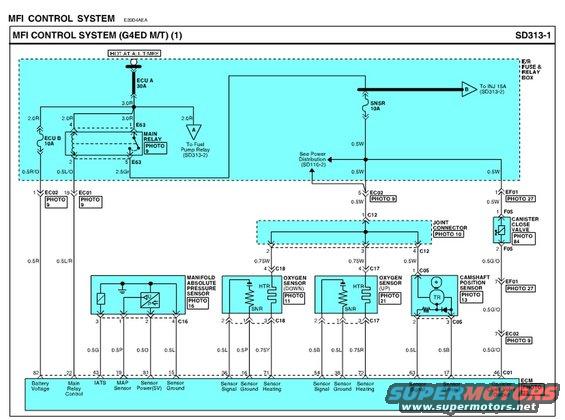
MFI control system wiring diagram (sheet 1) with color-coded wires for MAP, oxygen and camshaft sensors and connector references.
This document is page 1 of a Hyundai MFI (Multiport Fuel Injection) Control System wiring diagram, sheet SD313-1, for the G4ED engine with manual transmission (M/T), reference code E20D4AEA. It shows power distribution from the hot-at-all-times E/R (engine room) fuse and relay box, including the ECU A 30A fuse, ECU B 10A fuse, SNSR 10A fuse, and the Main Relay (connector E63), with branches to the Fuel Pump Relay and INJ 15A fuse (continued on SD313-2). The diagram traces wiring with gauge and color codes (e.g., 3.0R, 2.5Gr, 0.5W, 0.5G/O) through a joint connector (C12) to the Manifold Absolute Pressure Sensor (C16), downstream Oxygen Sensor (C18), upstream Oxygen Sensor (C17), Camshaft Position Sensor (C05), and Canister Close Valve (F05). Each sensor's heater (HTR) and signal (SNR) circuits are shown. At the bottom, ECM connector C01 pin assignments are listed: pin 82 battery voltage, 22 main relay control, 43 IATS, 19 MAP sensor, 81 sensor power (5V), sensor grounds and signals for both oxygen sensors, camshaft position sensor signal, and pin 46 canister close valve output. Photo callouts (PHOTO 9-84) reference connector location photos elsewhere in the manual.
Is this accurate? Sign in to help verify it.
Frequently asked questions
- What fuses power the ECM/MFI system on the G4ED M/T Accent?
- Per this diagram, power comes from the ECU A 30A fuse, ECU B 10A fuse, and SNSR 10A fuse in the fuse & relay box, all hot at all times, plus an INJ 15A fuse shown continuing to sheet SD313-2.
- Which ECM pin is battery voltage on connector C01?
- Pin 82 of ECM connector C01 is Battery Voltage; pin 22 is Main Relay Control.
- What are the ECM pins for the MAP sensor circuit?
- The MAP sensor (connector C16) connects to ECM pins 43 (IATS), 19 (MAP Sensor), 81 (Sensor Power 5V), and 15 (Sensor Ground), with wire colors 0.5G, 0.5P, 0.5O, and 0.5L.
- Which connectors are used for the upstream and downstream oxygen sensors?
- The downstream oxygen sensor uses connector C18 (ECM pins 36 signal, 16 ground, 71 heating) and the upstream oxygen sensor uses connector C17 (ECM pins 54 signal, 38 ground, 72 heating).
- What ECM pin controls the canister close valve?
- ECM pin 46 on connector C01 is the Canister Close Valve Output; the valve itself is at connector F05 (PHOTO 84) with a 0.5G/O wire.
Comments
More from this build




No comments yet.