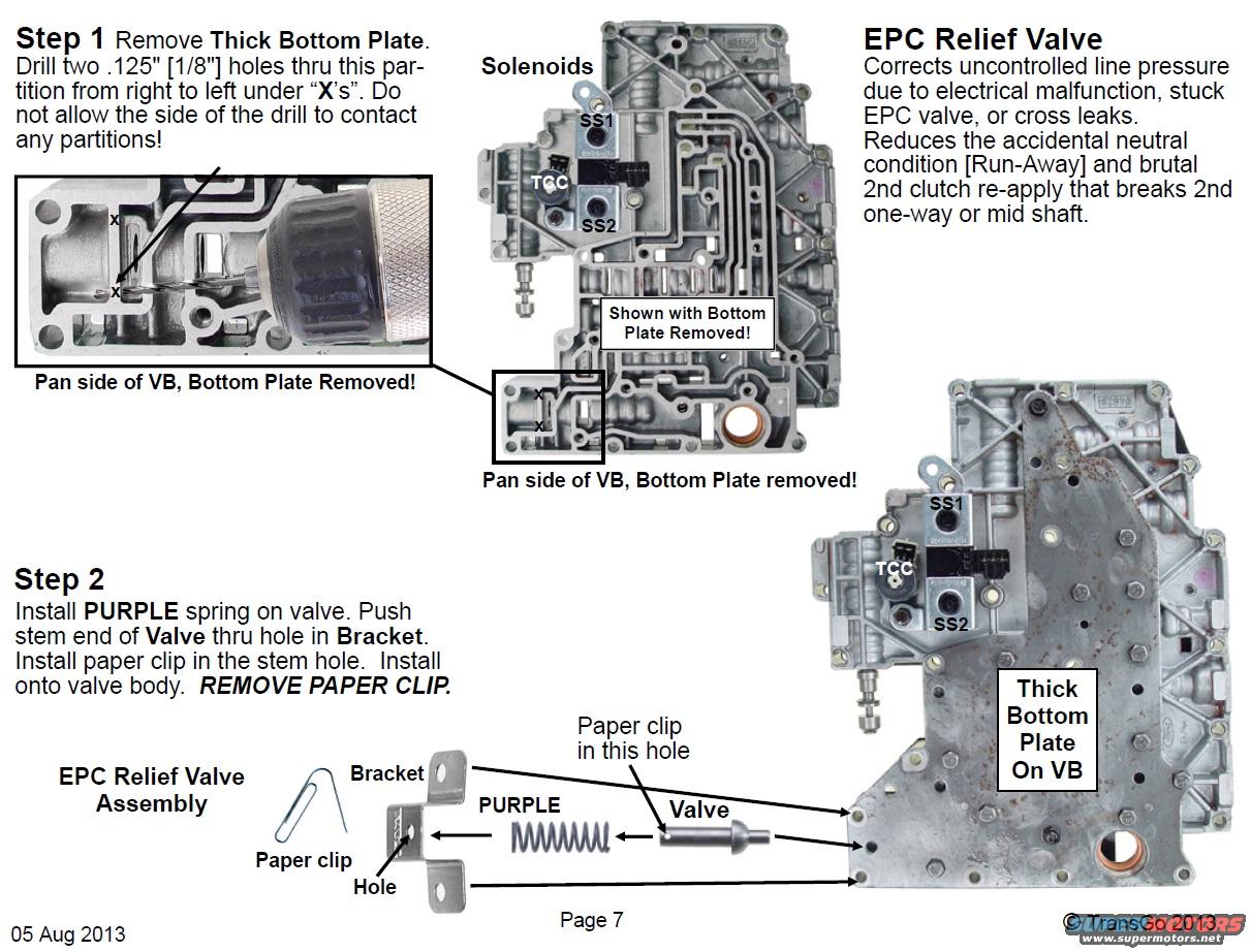
EPC relief valve install steps with drilled bottom plate, purple…
Reference · 1987-1991 F-250All 3 service procedures
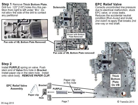

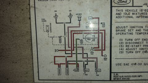
Step 1 drills two .125 in. holes in the thick bottom plate; Step 2 installs the EPC relief valve assembly with purple spring, bracket and paper clip.
Part of 1987-1991 Ford F-250 Service Procedures
Is this accurate? Sign in to help verify it.


No comments yet.