Vehicle Speed Sensor Circuit Schematic - LM2917N VSS for Traction Control/EMS
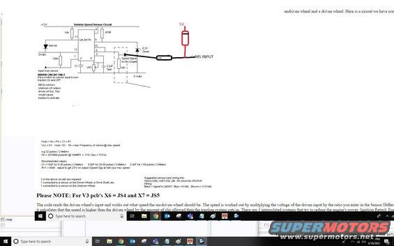
Electronic schematic of a vehicle speed sensor circuit with component values and accompanying explanatory text.
Part of 1988-2004 Lotus Esprit Schematics
This document is a screenshot of a Vehicle Speed Sensor (VSS) circuit schematic built around an LM 2917N frequency-to-voltage converter IC, intended for a wheel-speed / traction control application feeding an EMS (engine management system) input. The circuit runs on +12V, uses an IN4148 diode, 10K and 100K resistors, a 470R resistor, a 6.2V Zener, a 2.2uF tantalum capacitor, a variable resistor VR1, and outputs a speed signal to a de-coupler; a red hand-drawn annotation shows a 5V pull-up and 10K resistor feeding the EMS input. Notes state this is for the driven circuit only, and that two identical circuits are needed, one for a sensor on the driven wheel/drive shaft and one for the undriven wheel. Design formulas are given (Vout = Vin x Fin x C1 x R1) with an example of 32 pulses per 2 meters giving 715 Hz at 100 MPH, plus recommended C1 values (15nF, 6.8nF, or 3.3nF depending on pulses per 2 meters) and RV1 = 500K set for 2.5V at half max speed. A suggested sensor is the Omron E2EL-X2E1-DSL-2M (RS stock No. 378-8191) with wiring: Black = signal, Blue = 0V, Brown = +12V. A note explains how the code compares driven and undriven wheel speeds to trigger traction control via ignition retard and other power-reduction methods.
Is this accurate? Sign in to help verify it.
Frequently asked questions
- What IC is used in this vehicle speed sensor circuit?
- The circuit is built around an LM 2917N frequency-to-voltage converter IC, powered from +12V.
- How many of these circuits are required?
- Two circuits are required: one connected to a sensor on the driven wheel (or drive shaft), and one connected to a sensor on the undriven wheel.
- What sensor is suggested for this circuit?
- The Omron E2EL-X2E1-DSL-2M (RS stock No. 378-8191). Wiring: Black = signal to the LM2917, Blue = 0 Volts, Brown = +12 Volts.
- What are the recommended C1 and RV1 values?
- C1 = 15nF for 5-30 pulses per 2 meters, 6.8nF for 30-50 pulses per 2 meters, and 3.3nF for more than 50 pulses per 2 meters. RV1 = 500K, adjusted to give 2.5V on the Speed Sig output at half your maximum speed.
- How does the traction control logic use this signal?
- The code reads the driven wheel's input and calculates what speed the undriven wheel should be by multiplying the driven input voltage by an entered ratio. If the driven wheel speed exceeds the allowed slip, the traction system cuts in, reducing engine power via ignition retard and other interpolated systems.
Comments
More from this build

No comments yet.