Vehicle Speed Sensor Circuit Schematic - LM2917N VSS to 5V ECU Input
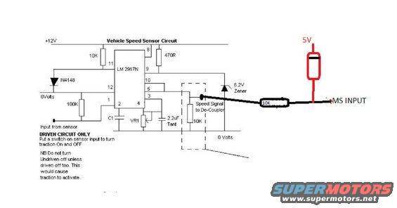
Electronic schematic of a vehicle speed sensor circuit built around an LM2917N with resistors, capacitors and a zener diode.
This document is a hand-annotated electronic schematic titled "Vehicle Speed Sensor Circuit." It shows a frequency-to-voltage/speed signal conditioning circuit built around an LM 2917N IC powered from +12V. Supporting components include a 10K resistor from the 12V rail to pin 11, a 470R resistor to pin 9, an IN4148 diode and 100K resistor on the sensor input side, C1 and VR1 (an adjustable trimmer) on pins 2 and 4, a 2.2uF tantalum capacitor, a 6.2V Zener diode on the output, and a 10K resistor to 0 Volts inside a dashed box producing a "Speed Signal to De-Coupler." A later annotation (bold black wire) shows the output tapped through an in-line 10K resistor with a red-drawn pull-up resistor to 5V, feeding an "MS INPUT" (likely a MegaSquirt or similar ECU input). Notes state the circuit is for the DRIVEN circuit only, recommend putting a switch on the sensor input to turn traction on and off, and caution not to turn the undriven sensor off unless the driven one is off too, or traction control would activate. The document contains no year, make, or model information itself.
Is this accurate? Sign in to help verify it.
Frequently asked questions
- What IC does this vehicle speed sensor circuit use?
- It uses an LM 2917N frequency-to-voltage converter IC, powered from +12V via pin 8.
- How is the speed signal output conditioned before the MS INPUT?
- The output passes through a 6.2V Zener and a 10K resistor to 0 Volts (Speed Signal to De-Coupler), then through an in-line 10K resistor on the wire to the MS INPUT, with a pull-up resistor to 5V shown in red.
- How can traction be turned on and off with this circuit?
- The notes say to put a switch on the sensor input to turn traction On and OFF; the circuit applies to the driven circuit only.
- What is the warning about the undriven sensor?
- NB: Do not turn Undriven off unless driven is off too, as this would cause traction to activate.
- What key components are on the sensor input side?
- An IN4148 diode and a 100K resistor between the input from the sensor and pins 12/1 of the LM 2917N, referenced to 0 Volts.
Comments
More from this build


No comments yet.