TIP120 vs IRLZ44N Pinout & Specs - MegaSquirt PWM Idle Valve Drive Schematic

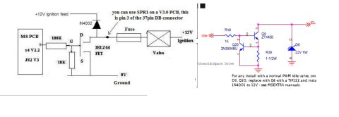
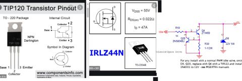
Composite reference: TIP120 and IRLZ44N pinouts/specs plus a PWM idle-valve driver schematic (R19 1K, R39 1-1/2W, D6 22V 1W, 2N5450/ZT450); note to swap Q4 for a TIP122 for normal PWM idle valves.
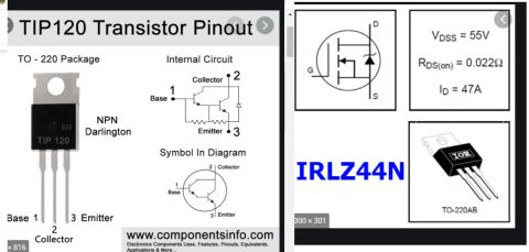
This document is a composite reference image comparing two transistor options — the TIP120 NPN Darlington transistor and the IRLZ44N N-channel power MOSFET — alongside a solenoid/spare drive schematic (typical of MegaSquirt/MSEXTRA idle valve output circuits). The left panel, sourced from www.componentsinfo.com, shows the TIP120 in a TO-220 package with pinout (1 Base, 2 Collector, 3 Emitter), its internal Darlington circuit, and its schematic symbol. The center panel shows the IRLZ44N in a TO-220AB package with key ratings: V_DSS = 55V, R_DS(on) = 0.022Ω, and I_D = 47A, plus its MOSFET symbol (G, D, S). The right panel is a 'Solenoid/Spare Drive' schematic showing an Idle-1 input through R19 (1K) driving Q4 (ZTX450) with Q20 (2N3904BU), R39 (1-1/2W), and D8 (22V 1W zener) leading to an IDL output. A note states that for installs with a normal PWM idle valve, D8 and Q20 should be omitted, Q4 replaced with a TIP122, and a 1N4001 installed to 12V, per MSEXTRA manuals. The document helps a builder choose and wire output transistors for a PWM idle valve drive circuit.
Is this accurate? Sign in to help verify it.
Frequently asked questions
- What is the pinout of the TIP120 transistor?
- In the TO-220 package, pin 1 is Base, pin 2 is Collector, and pin 3 is Emitter. It is an NPN Darlington transistor.
- What are the key specs of the IRLZ44N MOSFET?
- V_DSS = 55V, R_DS(on) = 0.022Ω, and I_D = 47A, in a TO-220AB package.
- How should the solenoid/spare drive circuit be modified for a normal PWM idle valve?
- Per the note: omit D8 and Q20, replace Q4 with a TIP122, and install a 1N4001 to 12V — see the MSEXTRA manuals.
- What components make up the solenoid/spare drive circuit shown?
- R19 (1K) on the Idle-1 input, Q4 (ZTX450), Q20 (2N3904BU), R39 (1-1/2W), and D8 (a 22V 1W zener) driving the IDL output.
Comments
More from this build

No comments yet.