Subaru COP Tach Input Adapter Schematic - NTE192/2N5551 High Voltage Tacho
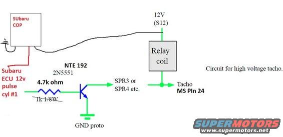
Schematic for a high-voltage tacho driver: Subaru COP/ECU 12V pulse on cyl #1 through 4.7k base resistor to an NTE192 (2N5551) transistor switching a relay coil, output to tacho / MS pin 24.
Part of 2012-2016 Subaru Impreza Schematics
This hand-annotated schematic shows a tachometer input adapter circuit for use with a Subaru coil-on-plug (COP) ignition setup and a MegaSquirt-style ECU. The Subaru ECU's 12V pulse signal from cylinder #1 (taken from the Subaru COP) feeds through a 4.7k ohm resistor (an earlier 1k 1/8W value is crossed out) into the base of an NTE 192 / 2N5551 NPN transistor. The transistor's emitter goes to ground (labeled 'GND proto'), and its collector output connects to 'SPR3 or SPR4 etc.' and drives a relay coil whose other side is tied to 12V (labeled S12). The junction at the relay coil output is labeled 'Tacho MS PIn 24', indicating the tach signal is fed to MegaSquirt pin 24. The drawing is captioned 'Circuit for high voltage tacho', indicating the relay coil arrangement generates a higher-voltage pulse suitable for driving a tachometer that requires a strong ignition-style signal. A reader learns the component values (4.7k resistor, NTE192/2N5551 transistor), the signal source (Subaru ECU 12V pulse, cylinder #1), the power connection (12V via S12), and the output destination (MS Pin 24 tach input).
Is this accurate? Sign in to help verify it.
Frequently asked questions
- What transistor is used in this Subaru COP tach adapter circuit?
- An NTE 192, also labeled 2N5551.
- What resistor value goes on the transistor base input?
- 4.7k ohm; an earlier 1k 1/8W value is shown crossed out.
- Where does the tach signal come from?
- The Subaru ECU 12V pulse for cylinder #1, taken from the Subaru COP (coil-on-plug).
- Where does the output of the circuit go?
- The transistor output goes to SPR3 or SPR4 etc., and through a relay coil (fed by 12V at S12) to the Tacho at MS Pin 24.
- What is this circuit for?
- The drawing is captioned 'Circuit for high voltage tacho', it adapts the Subaru COP/ECU 12V pulse to drive a tachometer requiring a high-voltage signal.
Comments
More from this build



No comments yet.