Home/
Registry/
Ford/
Explorer/
2011-2019/
2016 Ford Explorer/
Photo
supermotors.net/registry/media/1172222
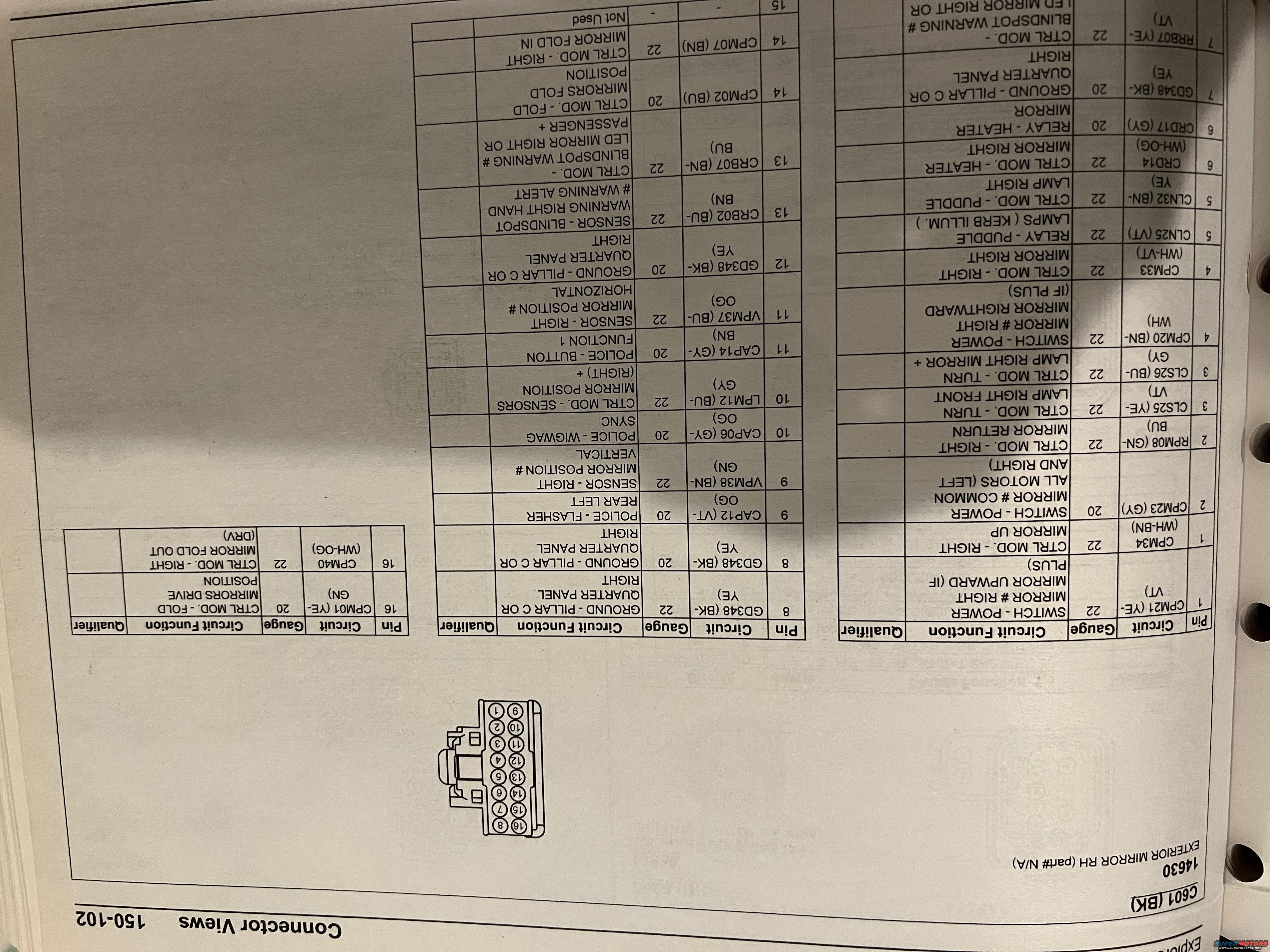
2016 Ford Explorer C601 Connector Pinout - RH Exterior Mirror Wiring Diagram
Reference · 2011-2019 ExplorerAll 3 wiring diagrams
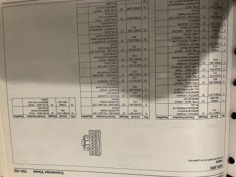
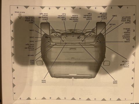
Connector pinout chart with wire colors and circuit functions for a mirror module connector
Part of 2011-2019 Ford Explorer Wiring Diagrams
This document is a connector pinout page ("Connector Views 150-102") from a Ford wiring/EVTM-style manual, photographed upside-down. It details connector C601 (BK), which serves component 14630, EXTERIOR MIRROR RH (part# N/A), i.e., the right-hand exterior side mirror. A drawing of the 16-cavity connector shows pin numbering in two rows (1-8 and 9-16). The accompanying tables list, for each pin, the circuit designation, wire color code, wire gauge, circuit function, and qualifier. Functions include power-mirror switch signals (mirror up, rightward, common motor return), turn-signal lamp for the mirror, puddle lamp and relay feeds, heated mirror control and relay, multiple grounds (GD348 to the C-pillar or right quarter panel), blind-spot warning sensor and LED indicator circuits, mirror position sensors (horizontal and vertical), power-fold mirror drive/fold position and fold in/out control, plus police-package circuits (rear flasher, wigwag sync, button function 1). Pin 15 is not used. Circuit codes include CPM21, CPM34, CPM23, RPM08, CLS25, CLS26, CPM20, CPM33, CLN25, CLN32, CRD14, CRD17, GD348, RRB07, CAP12, VPM38, CAP06, LPM12, CAP14, VPM37, CRB02, CRB07, CPM02, CPM07, CPM01, and CPM40, with wire colors such as YE-VT, WH-BN, GY, BU-GY and gauges of 20 or 22 AWG.
Is this accurate? Sign in to help verify it.
Frequently asked questions
- What connector is shown in this diagram?
- Connector C601 (BK), a 16-pin connector for component 14630, the EXTERIOR MIRROR RH (right-hand exterior mirror); part# is listed as N/A.
- Which pin of C601 is the ground for the right exterior mirror?
- Ground circuit GD348 (BK-YE), 'GROUND - PILLAR C OR QUARTER PANEL RIGHT', appears on pins 7, 8, and 12 in 20 or 22 gauge.
- Which pins control the power-fold mirror function?
- Pin 14 carries CPM02 (BU, 20 ga) 'CTRL MOD. - FOLD MIRRORS FOLD POSITION' and CPM07 (BN, 22 ga) 'CTRL MOD. - RIGHT MIRROR FOLD IN'; pin 16 carries CPM01 (YE-GN, 20 ga) 'CTRL MOD. - FOLD MIRRORS DRIVE POSITION' and CPM40 (WH-OG, 22 ga) 'CTRL MOD. - RIGHT MIRROR FOLD OUT'.
- Where are the blind-spot warning circuits on this connector?
- Pin 13 has CRB02 (BU-BN, 22 ga) 'SENSOR - BLINDSPOT WARNING RIGHT HAND # WARNING ALERT' and CRB07 (BN-BU, 22 ga) 'CTRL MOD. - BLINDSPOT WARNING # LED MIRROR RIGHT'; a related RRB07 (YE-VT, 22 ga) circuit appears on pin 7.
- Which pin feeds the heated mirror?
- Pin 6: CRD14 (WH-OG, 22 ga) 'CTRL MOD. - HEATER MIRROR RIGHT' and CRD17 (GY, 20 ga) 'RELAY - HEATER MIRROR'.
- Are any pins unused on connector C601?
- Yes, pin 15 is listed as 'Not Used'.


No comments yet.