Nissan Micra Service Manual GI-6: Wiring Diagram Symbols & Wire Color Codes
Service manual legend page explaining wiring-diagram symbols: connectors, ignition switch power, switches, body/instrument grounds, location numbers and wire color codes.
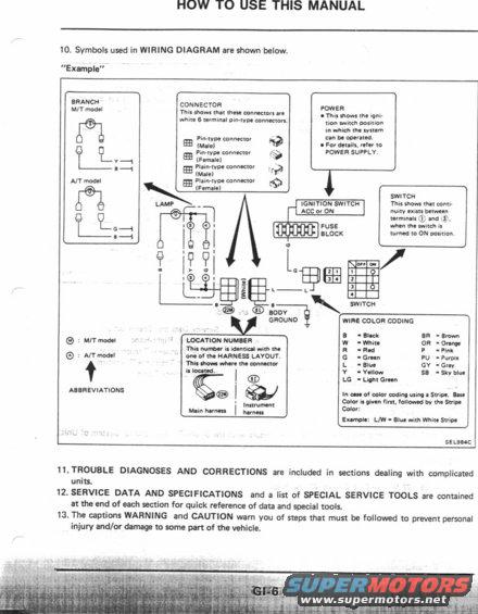
This is page GI-6 from the General Information section of a Nissan factory service manual, titled "HOW TO USE THIS MANUAL." Item 10 explains the symbols used in the manual's wiring diagrams via an annotated example. The example diagram illustrates: branch circuits distinguished by M/T (manual transmission) and A/T (automatic transmission) models; connector symbols showing white 6-terminal pin-type connectors and the difference between pin-type and plain-type connectors, male and female; a POWER block indicating the ignition switch position (e.g. ACC or ON) in which a system can operate, with reference to the POWER SUPPLY section; the fuse block symbol; a switch continuity chart showing how terminal continuity is indicated in each switch position; body ground symbols; and location numbers (e.g. 22M for main harness, 81 for instrument harness) that correspond to the HARNESS LAYOUT diagrams. A wire color coding legend defines abbreviations: B=Black, W=White, R=Red, G=Green, L=Blue, Y=Yellow, LG=Light Green, BR=Brown, OR=Orange, P=Pink, PU=Purple, GY=Gray, SB=Sky blue, with striped wires written base color first (e.g. L/W = Blue with White Stripe). Items 11–13 explain that trouble diagnoses, service data/specifications, special service tools listings, and WARNING/CAUTION captions are included throughout the manual. Reference code SEL984C appears on the diagram.
Is this accurate? Sign in to help verify it.
Frequently asked questions
- What do the wire color abbreviations mean in Nissan wiring diagrams?
- B=Black, W=White, R=Red, G=Green, L=Blue, Y=Yellow, LG=Light Green, BR=Brown, OR=Orange, P=Pink, PU=Purple, GY=Gray, SB=Sky blue.
- How are striped wires labeled, like L/W?
- The base color is given first, followed by the stripe color. Example: L/W = Blue with White Stripe.
- What does the location number on a connector mean?
- The location number is identical with the one on the HARNESS LAYOUT and shows where the connector is located, e.g. 22M = Main harness, 81 = Instrument harness.
- What does the POWER block in the wiring diagram indicate?
- It shows the ignition switch position (such as ACC or ON) in which the system can be operated; for details, refer to POWER SUPPLY.
- How is switch continuity shown in the diagrams?
- A switch table shows that continuity exists between specific terminals — e.g. between terminals 1 and 3 when the switch is turned to the ON position.
Comments
More from this build


No comments yet.