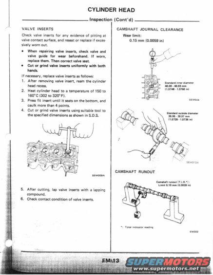
This diagram illustrates the inspection process for a cylinder head, including valve inserts and camshaft journal clearance.
" Illhls we: m CYLINDER HEAD VALVE INSERTS Check valve inserts for any evidence of pitting at valve contact surface, and reseat or replace if exces- sively worn out. I When repairing valve inserts, check valve and valve guide for wear beforehand. If worn, replace them. Then correct valve seat. - Cut or grind valve insem uniformly with both hands. If necessary, replace valve inserts as follows: 1. After removing valve insert, ream the cylinder head recess. 2. Heat cylinder head to a temperature of 150 to 160C (302 to 320"F). 3. Press fit insert until it seats on the bottom, and caulk more than 4 poinls. 4. Cut or grind valve inserts using suitable tool to the specified dimensions as shown in 5.0.5. SEMDUSA 5. After cutting, lap valve inserts with a lapping compound. 6. Check contact condition of valve inserts. Inspection (Cont'd) CAMSHAFT JOURNAL CLEARANCE Wear limit: 0.15 mm (0.0059 in) H 7), ' Standard innurdiamater mo-40.0: mm l (1.5748 15750 in) SEME-u sand-rd ounido dim-m 35.55 - 19.97 mm (15728 -1573in| CAMSHAFT RUNOUT E-mmuh runoul [T.l.R.'l: Limit DJO mm (0.0039 in) ~: Total ll'ldlCaKDf reading Emauz
Comments
More from this build


No comments yet.