Cylinder head inspection and assembly procedures are detailed in this diagram from a service manual.
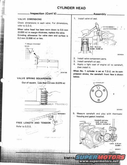
.4: Inspection ( Cont'dI VALVE DIMENSIONS Check dimensions in each valve. For dimensions, refer to 5.0.5. } When valve head has been worn down to 0.5 mm 7 (0.020 in) in margin thickness, replace the valve. Grinding allowance for valve stem end surface is 0.2 mm (0.008 in) or less. 1' (Margin [hmknlssl " semen VALVE SPRING SOUAREN 53/ ~ . . v Out of square; Less dunz mm [0.079 in) FREE LENGTH 'AND TENSION gf/ Refer to S.D.S. CYLINDER HEAD Assembly 1. Install valve oil seal. KVIDIOSSOO ( l and KV10|07500( l r 13 - 15.1 mm ,, (0.5a: nsee in) SEMQSA 2. Install valve component parts. 3. Install camshaft oil seal. 4. Apply a light coat of engine oil to camshaft, then install it. WhenNu. 1 cylinder is set at T.D.C. on is com- pression stroke, die camshaft front face is shown below. Knock Pin sEMee. 5. Measure camshaft end play with thermosta housing and gasket installed. Cam-run um play 0.03 - 0.3! mm , (0.0012 - 0.0112 in] Limit: 0.15 mr [0.059 i!
Comments
More from this build


No comments yet.