Diagram illustrates the assembly process for transmission components, detailing tool usage.
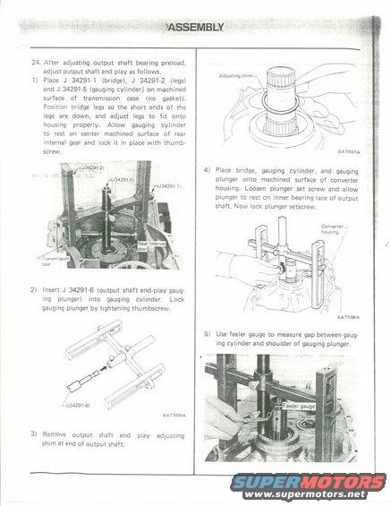
massmsm , 1: 24. After adiusting output shaft bearing preload, adjust output shaft end play as follows. ll Place J 3429171 (bridge), J 34291-2 (legs) and J 342915 (gauging cylinder) on machined surface of transmission case (no gasket). Position bridge legs so the short ends of the legs are down, and adjust legs to fit onto housing properly. Allow gauging cylinder to rest on center machined surface of rear internal gear and lock it in place with thumb screw. 2) Insert J 342916 (output shaft endrplay gaug- ing plunger) into gauging cylindert Lock gauging plunger by tightening thumbscrew. 4 3429le SATSDEA 3i Remove output shaft and play adjusting shim at end of output shaft Adjustlng 5mm- ng [WT // V\ 4/ //// l ' / l l l/ SAT507A 4i Place bridge, gauging cylinder, and gauging plunger onto machined surface of converter housing. Loosen plunger set screw and allow plunger to rest on inner bearing race of output shaft Now lock plunger setscrew. Converter, nausmg / l l SATSOGA 5) Use feeler gauge to measure gap between gaug- ing cylinder and shoulder of gauging plunger.
Comments
More from this build


No comments yet.