This document page details the assembly and adjustment procedures for a vehicle's front axle wheel hub and knuckle.
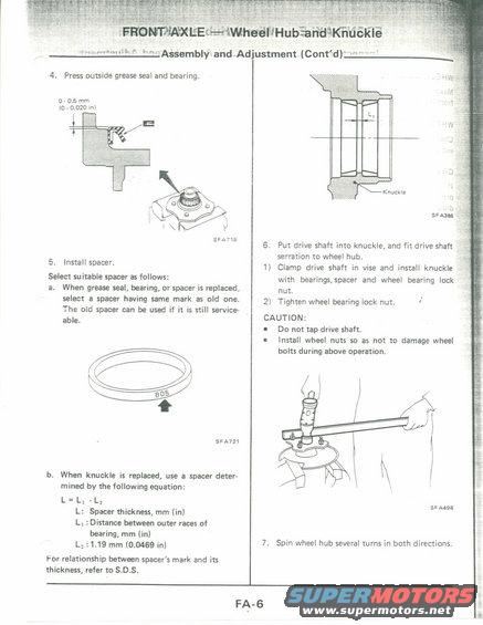
v v mWEEaiWhedWHubanqKce $ASembly and Ad' ustment (Cont' -d) 4. Press outside grease seal and bearing. W L O 0.5 mm [0 , 0.020 ml LI Wham l 5 6. Put drive shaft into knuckle, and fit drive shaft serration to wheel hub. 5' "ma spacer. ll Clamp drive shaft in vise and install knuckle 59'9 suitable SPGCSYBfOHOWSI with bearings, spacer and wheel bearing lack a. When grease seal, hearing, or spacer is replaced, nut. select a spacer having same mark as old one. 2, Tighten wheel bearing lock nut. I The old spacer can be used if it is still service- able. CAUTION: 0 Do not tap drive shaft. I Install wheel nuts so as not to damage wheel A bolts during above operation. A 5FA721 b. When knuckle is replaced, use a spacer deter- mined by the following equation: L=L,-L, L: Spacer thickness, mm (in) 93 Lx :Distance between outer races of bearing, mm (in) L: :1.19 mm (0.0459 in) 7. Spin wheel hub several turns in both directions. For relationship between spacers mark and its thickness, refer to S.D.S. FA-G
Comments
More from this build


No comments yet.