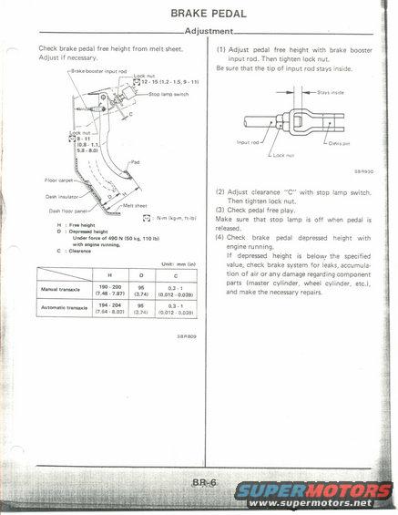
This document provides instructions and diagrams for adjusting a vehicle's brake pedal, detailing measurements for free height and clearance.
BRAKE PEDAL Check brake pedal free height from melt sheet. Adjust if necessary. Lock nut Brake banner input rad M12-15lL1-L5,5-H) Stop lamp switch Luck nut Mi:- Il Melt sheet {L}: N-m (kg-m, mm H : Fm mm D : Donnd mm Ulldu run- of m N (50 kg, 11mm with "in. mnnim. c : Channel Unit: mm (in) Adjustment H D c 90200 95 0.34 Man-Ml ml- (7.41: 7.3 (3.74) (0.012 - 0.039) Alum-tic tnnmll 9 ' 2m 95 '3 ' 1 (7.6! ~ 8.03) 4.7- (0.012 , 0.035) senses (1) Adjust pedal free height with brake booster input rod. Then tighten lock nut, Be sure that the tip of input rod stays inside. +Stays inside D in. Lock nul sensaa i2) Adiust clearance "C with stop lamp switch. Then tighten lock nut. (3) Check pedal free play, Make sure that stop lamp is off when pedal is released. (4) Check brake pedal depressed height with engine running. If depressed height is below: the specified value, check brake system for leaks, accumula- tion of air or any damage regarding component parts (master cylinder, wheel cylinder, etc.), and make the necessary repairs.
Comments
More from this build


No comments yet.