Line-art cutaway diagram of a vacuum brake booster
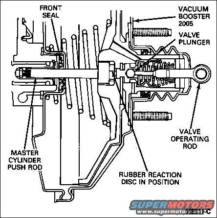
Booster Operation
Under normal driving conditions, the engine's intake manifold vacuum passes to both sides of the brake booster diaphragm via the large vacuum hose & plastic right-angle check valve in the front of the booster. It stops at the rear (in-cab) vent valve (vacuum bleed port) which is closed when the pedal is not applied. Since pressure is equal within the booster's steel housing, there is no force applied to the diaphragm or pushrod.
When the pedal is first applied, the equalizer valve (between the 2 sides of the diaphragm) closes, maintaining engine vacuum on the front of the diaphragm, but blocking off the vacuum supply to the rear. Whatever vacuum pressure is behind the diaphragm remains until the pedal moves farther. As the pedal continues to move forward, the vacuum bleed port begins to open, allowing atmospheric pressure to enter the rear chamber. Since the front chamber is still under vacuum, a force develops across the diaphragm, which is applied to the pushrod, assisting the operator in pushing against the master cylinder piston.
The vacuum bleed port allows only the required amount of atmospheric pressure into the booster chamber. This is determined by the force applied to the brake pedal by the driver. The harder the driver applies the brake, the more atmospheric pressure allowed into the booster chamber, and the greater the vacuum boost. Once the level of boost corresponds to the force applied to the brake pedal the bleed port on the pushrod closes, thus maintaining the level of vacuum in the chamber.
When the pedal stops, both valves close, holding the last pressure differential in the booster, allowing the operator to maintain high brake pressure with little effort.
When the pedal is moved rearward, the operating valve pushrod moves back, opening the vacuum port to the rear chamber, which evacuates the air & moves the diaphragm, pushrod, pedal, & master cylinder piston back to lower the brake pressure.
When the pedal is fully released, the equalized vacuum in both chambers allows the return spring to force the pushrod away from the master cylinder piston, and the pedal to the full up position.
Is this accurate? Sign in to help verify it.
Comments
More from this build









No comments yet.