Nissan starter reassembly service manual page with diagrams and…
Scanned service manual page titled 'STARTING SYSTEM — Starter — Reassembly,' detailing grease application points, gear case end play (0.1-0.5 mm), and pinion clearance measurements for M/T and A/T models. Includes line diagrams of the starter, magnetic switch wiring, adjusting plate, and gear case, with reference codes like SEL049D and page marker EL-21.
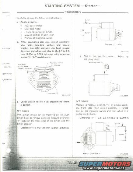
STARTING SYSTEM Starter Carefully observe the following instructions a, Apply grease to: Rear cover metal Gear case metal Frictional surface of pinion Moving portion of shift lever Plunger of magnetic switch b. After assembling gear case, pinion assembly, idler gear, adjusting washers and center bracket, turn idler gear with your hand in axial am calmer direction and adjust end play to the 0.1 to 0.5 mm (0.004 to 0.020 in) range using adjusting washerls). (A/T models only) c Ad n "mam End pl": / lusxfg: =r sewn on a 0.5 mm (0.004 - mm in] i i ,ommuta- i l Undercut i SELDABD l l i Gear cash 4 1:. Check pinion to see if its engagement length ' is correct ' M/T models With pinion driven out by magnetic switch, push pinion back to remove slack and measure clearance "E" between the front edge of the pinion and the pinion stopper. Clearance "12": 0.3 - 2.5 mm (0.012 - 0.098 in) Reassembly Clearance "E" for- sELsaze - Not in the specified value Adjust by adjusting plate. Aujumng plate A SELGJBE A/T models Measure difference in length U" of pinion assemr blv front edge when pinion assembly is forced out by the magnetic switch and then when it is pulled out by hand. Difference "E": 0.3 - 2.5 mm (0,012 0.098 in)
Is this accurate? Sign in to help verify it.
Comments
More from this build


No comments yet.