Home/
Registry/
Ford/
Bronco/
1966-1977/
1974 Ford Bronco/
Photo
supermotors.net/registry/media/307987
1974 Ford Bronco Parking Brake Cable Routing Diagram - Ford FoMoCo Exploded View

Reference · 1966-1977 BroncoAll 140 exploded parts diagrams
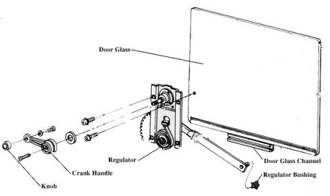
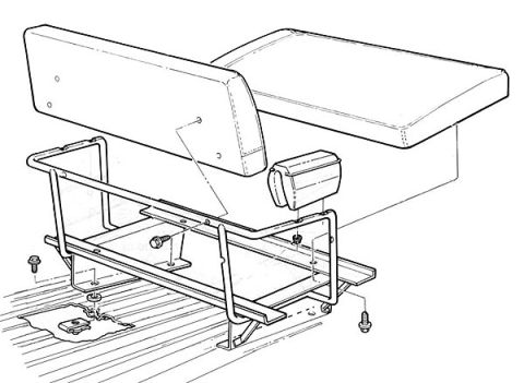
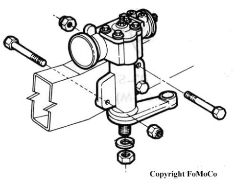
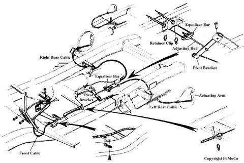
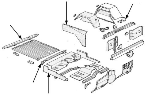
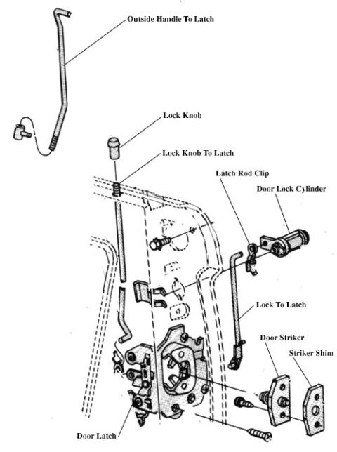
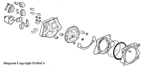
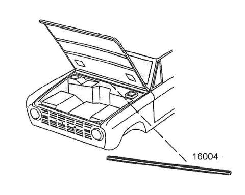
Exploded routing diagram of parking brake front and rear cables, equalizer bar and pivot brackets.
Part of 1966-1977 Ford Bronco Exploded Parts Diagrams
This document is a Ford factory (FoMoCo copyright) exploded/routing illustration of the parking brake (emergency brake) cable system on a Ford Bronco chassis, uploaded to a 1974 Ford Bronco gallery. The line drawing shows the underbody frame viewed in perspective, with arrows indicating the routing and attachment points of the parking brake components. Labeled parts include the Front Cable, Right Rear Cable, Left Rear Cable, Equalizer Bar (shown both in the main routing view and in a detailed inset at upper right), Retainer Clip, Adjusting Rod, Pivot Bracket (labeled in two locations), and Actuating Arm. The upper-right inset provides a close-up of how the equalizer bar, retainer clip, adjusting rod, and pivot bracket assemble together, while the main view shows how the front cable runs from the pedal/lever area at the front of the frame back to the equalizer, splitting into left and right rear cables leading to the rear drum brakes via the actuating arm. No part numbers, torque specs, or year/model text appear on the drawing itself. A reader can learn the correct routing, component names, and relative positions of all parking brake linkage parts for reassembly or adjustment.
Is this accurate? Sign in to help verify it.
Frequently asked questions
- What parking brake components are shown in this Ford Bronco diagram?
- The diagram labels the Front Cable, Right Rear Cable, Left Rear Cable, Equalizer Bar, Retainer Clip, Adjusting Rod, Pivot Bracket, and Actuating Arm.
- How does the equalizer bar assembly connect in the parking brake system?
- An inset detail shows the Equalizer Bar attached via a Retainer Clip to the Adjusting Rod, which connects to the Pivot Bracket.
- Where do the parking brake cables route?
- The Front Cable runs from the front of the frame to the Equalizer Bar at the Pivot Bracket, and separate Left Rear and Right Rear Cables continue rearward, with the left rear cable connecting to an Actuating Arm.
- Is this an official Ford diagram?
- Yes, the illustration is marked 'Copyright FoMoCo' (Ford Motor Company).
No comments yet.