Home/
Registry/
Ford/
Bronco/
1966-1977/
1974 Ford Bronco/
Photo
supermotors.net/registry/media/307988
1974 Ford Bronco Steering Gear Box Exploded Diagram - Mounting & Pitman Arm

Reference · 1966-1977 BroncoAll 140 exploded parts diagrams
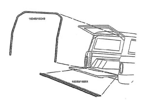
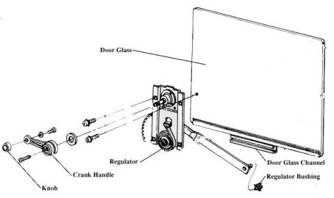
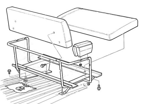
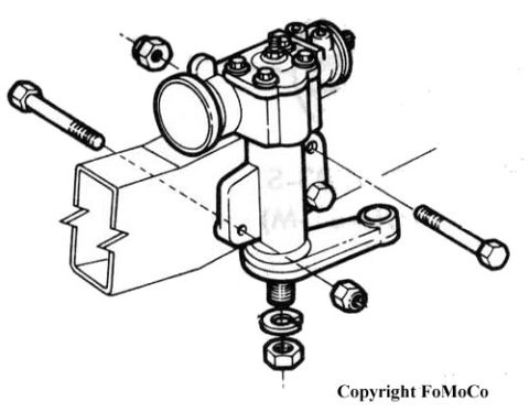
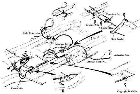
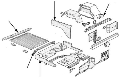
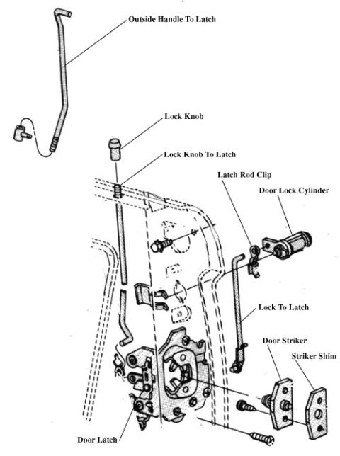
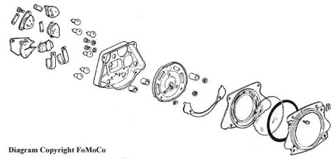
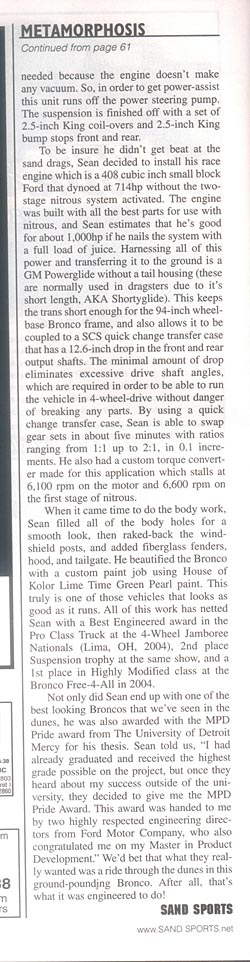
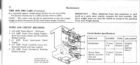
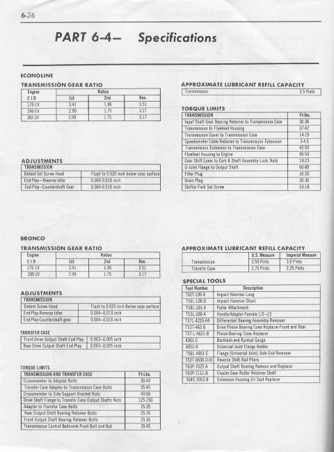
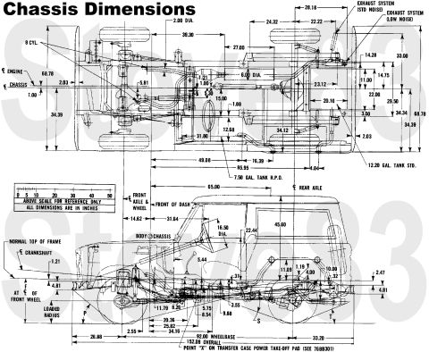
Exploded parts diagram of a steering gear box with mounting bolts, nuts and pitman arm.
Part of 1966-1977 Ford Bronco Exploded Parts Diagrams
This document is an exploded-view illustration (credited 'Copyright FoMoCo') showing a steering gear box assembly and its mounting hardware, uploaded to a 1974 Ford Bronco gallery under the filename 'pwrsteeringbx.jpg'. The drawing depicts the steering box unit with its top cover and adjuster hardware, the sector shaft extending downward through the housing, and the pitman arm attached at the bottom with a lock washer, flat washer, and castellated-style retaining nut. Two long mounting bolts with lock washers are shown positioned to pass through the frame rail (drawn as an open rectangular box section) into the steering gear housing, along with corresponding hex nuts. Dashed alignment lines indicate how the fasteners and components assemble. There are no part numbers, torque specifications, callout numbers, or legend text visible on this scan, it is purely a pictorial assembly reference. A reader can learn the general arrangement and order of assembly of the steering gear to the frame and the pitman arm to the sector shaft, useful when removing or reinstalling the steering box on an early Ford Bronco or similar Ford vehicle, but must consult other documentation for fastener sizes, torque values, and part numbers.
Is this accurate? Sign in to help verify it.
Frequently asked questions
- What does this diagram show?
- An exploded view of a steering gear box assembly, including the steering box, two frame mounting bolts with lock washers and nuts, and the pitman arm secured to the sector shaft with a lock washer, washer, and nut.
- How does the steering box mount to the frame in this diagram?
- Two long bolts with lock washers pass through the boxed frame rail section into the steering gear housing, shown with dashed alignment lines.
- How is the pitman arm retained according to the illustration?
- The pitman arm slides onto the splined sector shaft at the bottom of the box and is retained by a lock washer, flat washer, and a hex nut.
- Are there any part numbers or torque specs in this document?
- No. The only text visible is 'Copyright FoMoCo'; there are no part numbers, callouts, or torque values.
No comments yet.