Home/
Registry/
Ford/
Bronco/
1966-1977/
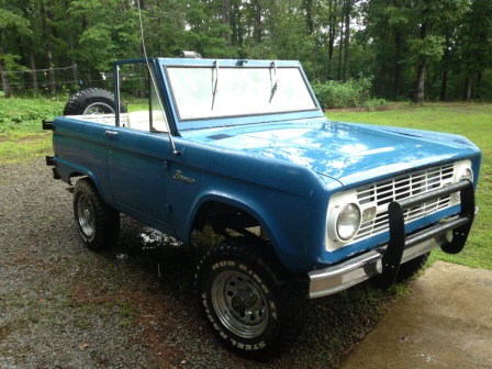
1974 Ford Bronco/
Photo
supermotors.net/registry/media/308005
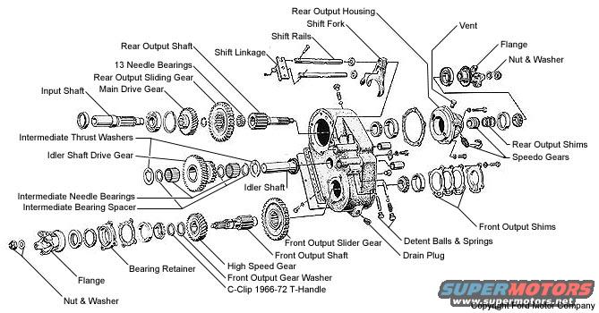
Ford Bronco Transfer Case Exploded Parts Diagram - Dana 20 Component Names
Reference · 1966-1977 BroncoAll 140 exploded parts diagrams
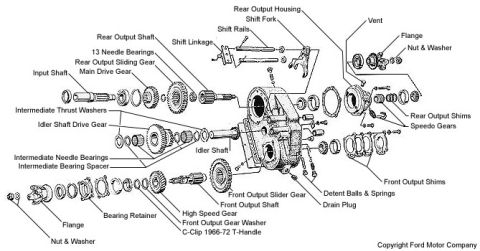
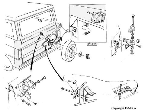
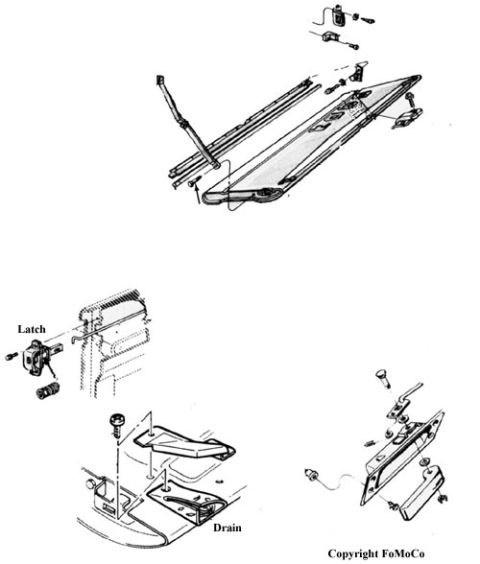
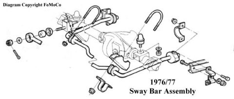

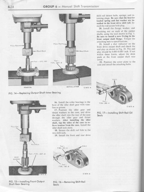
Exploded parts breakdown of a transfer case showing input/output shafts, gears, bearings, shift rails and shims.
Part of 1966-1977 Ford Bronco Exploded Parts Diagrams
This document is an exploded parts diagram of a Ford transfer case, credited "Copyright Ford Motor Company." It illustrates the complete internal assembly of the transfer case with callout labels identifying each major component. Labeled parts include the input shaft, main drive gear, rear output shaft, rear output sliding gear, 13 needle bearings, and rear output housing with its shift fork, shift rails, and shift linkage. The intermediate/idler assembly is detailed with the idler shaft, idler shaft drive gear, intermediate thrust washers, intermediate needle bearings, and intermediate bearing spacer. The front output section shows the front output shaft, front output slider gear, high speed gear, front output gear washer, bearing retainer, front output shims, detent balls & springs, and drain plug. Rear output shims, speedo gears, a vent, and both front and rear flanges with nuts and washers are also identified. One callout notes a "C-Clip 1966-72 T-Handle," indicating applicability to 1966-72 T-handle shifter configurations. The diagram is useful for identifying parts by name and understanding the order and orientation of components during transfer case disassembly, rebuild, or reassembly. No part numbers, torque specifications, or fluid capacities are given, only component identification.
Is this accurate? Sign in to help verify it.
Frequently asked questions
- What parts make up the intermediate (idler) gear assembly in this Ford transfer case?
- The diagram shows the idler shaft, idler shaft drive gear, intermediate thrust washers, intermediate needle bearings, and an intermediate bearing spacer.
- How many needle bearings are used on the rear output shaft?
- The diagram calls out 13 needle bearings near the rear output shaft and main drive gear.
- Where are the shims located in this transfer case?
- Shims are shown in two locations: rear output shims (near the speedo gears at the rear output housing) and front output shims (at the front output bearing retainer area).
- Does the diagram show the shift components?
- Yes. It labels the shift fork, shift rails, shift linkage, and the detent balls & springs.
- What does the C-clip callout refer to?
- A callout labeled 'C-Clip 1966-72 T-Handle' points to the front output gear washer area, indicating the C-clip applies to 1966-72 T-handle shifter versions.

No comments yet.