Home/
Registry/
Ford/
Ranchero/
1972-1976/
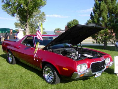
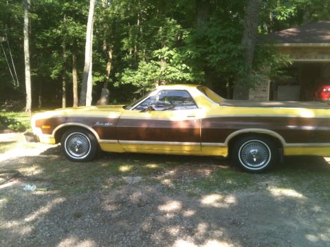
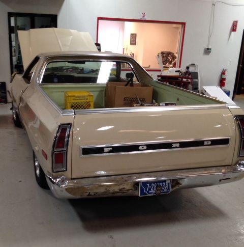
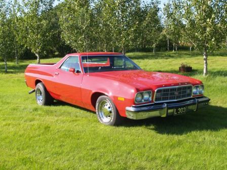
1972 Ford Ranchero/
Photo
supermotors.net/registry/media/498706
Ford V8 Distributor Rotor Phasing Diagram - Firing Order 1-3-7-2-6-5-4-8

Hand-drawn firing-order and crankshaft-degree diagram mapping cylinders 1 through 8 around a circle with their ignition timing positions.
This is a hand-drawn schematic (filename rotorphase.jpg) showing distributor rotor phasing for a V8 engine. Eight circles represent the distributor cap terminals for cylinders, each labeled with its cylinder number and the distributor rotation angle at which it fires: #1 at TDC (0°), #3 at 45°, #7 at 90°, #2 at 135°, #6 at 180°, #5 at 225°, #4 at 270°, and #8 at 315°. Reading the sequence of increasing angles gives the firing order 1-3-7-2-6-5-4-8. In the center is a sketched multi-lobed distributor cam/reluctor with radiating lines marked at degree intervals (24°, 45°, 72°, 96°, 120°, 144°, 168°, 192°, 216°, 240°, 264°, 288°, 312°, 336°), showing intermediate points of rotor rotation between firing events (nominally every 24° in a pattern, with a 45° mark aligning to cylinder #3). Straight lines pass through opposing cylinder terminals to illustrate the geometric relationship between cap terminal positions and rotor angle. A reader can use this diagram to understand how the rotor position corresponds to each spark plug terminal and to verify correct rotor phasing when setting up or diagnosing a Ford V8 distributor. The document itself carries no year, make, part number, or engine identification text.
Is this accurate? Sign in to help verify it.
Frequently asked questions
- What firing order does this rotor phasing diagram show?
- Reading the cylinder circles in order of increasing distributor angle (0°, 45°, 90°, 135°, 180°, 225°, 270°, 315°) gives the firing order 1-3-7-2-6-5-4-8.
- At what distributor angle does cylinder #1 fire?
- Cylinder #1 fires at TDC, marked as 0° on the diagram.
- How many degrees of distributor rotation separate each cylinder's firing point?
- Each cylinder terminal is 45° apart in distributor rotation: #1 at 0°, #3 at 45°, #7 at 90°, #2 at 135°, #6 at 180°, #5 at 225°, #4 at 270°, and #8 at 315°.
- What do the small degree numbers around the center of the drawing represent?
- They mark intermediate rotor/cam angles between firing points, labeled 24°, 45°, 72°, 96°, 120°, 144°, 168°, 192°, 216°, 240°, 264°, 288°, 312°, and 336° around the multi-lobed center sketch.
Comments
More from this build



No comments yet.