Home/
Registry/
Ford/
Ranchero/
1972-1976/
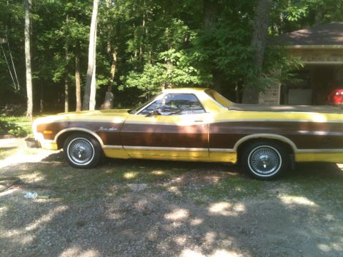
1972 Ford Ranchero/
Photo
supermotors.net/registry/media/796039
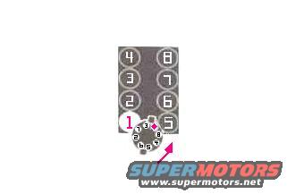
Ford V8 Distributor Cap & Cylinder Numbering Diagram - #1 Plug Wire Position
Reference · 1972-1976 RancheroAll 8 schematics
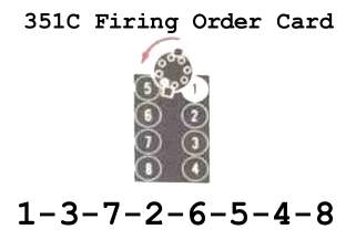
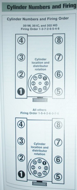

Schematic diagram showing the cylinder numbering layout of a V8 engine with cylinders 1 through 8 arranged in two banks.
Part of 1972-1976 Ford Ranchero Schematics
This scanned schematic, titled by its uploader as 'DizzySet.jpg', is a distributor setup/firing-order reference diagram for a V8 engine. It shows a top-down view of an eight-cylinder engine block with two banks of cylinders: cylinders 4, 3, 2, 1 on one bank and 8, 7, 6, 5 on the other. Superimposed at the front cylinder (cylinder 1) is a circular distributor cap illustration with its eight terminal positions numbered around the circumference. The number 1 terminal is highlighted in pink with a diamond marker, indicating the position of the number-one spark plug wire on the cap, and an arrow at the lower right suggests rotor rotation direction or an alignment reference. A reader can learn the cylinder numbering convention for the engine and how the spark plug wires are ordered around the distributor cap relative to the highlighted #1 terminal. The document contains no written text, part numbers, year statements, or engine displacement callouts, it is purely a numeric pictorial reference. Companion files in the same album (firing orders, distributor specs, ignition system specs) suggest it accompanies a broader ignition tune-up reference set for a 1972 Ford, likely a 351 Cleveland-family engine based on album context.
Is this accurate? Sign in to help verify it.
Frequently asked questions
- How are the cylinders numbered in this diagram?
- One bank is numbered 4, 3, 2, 1 from rear to front and the other bank is numbered 8, 7, 6, 5, showing a V8 layout.
- Where is the number 1 terminal on the distributor cap?
- The #1 terminal is highlighted in pink with a diamond marker on the distributor cap, located adjacent to cylinder 1 at the front of the engine.
- What is the order of terminals shown around the distributor cap?
- Reading around the cap from the highlighted #1 terminal, the visible numbers are 1, 3, 7, 2, 6, 5, 4, with one number partially illegible (likely 8).
- Does this diagram include any torque specs, part numbers, or text instructions?
- No: the document is purely pictorial, containing only cylinder and distributor terminal numbers plus a directional arrow.

No comments yet.